SEC-H-600 SECURITY CONTROLLER
21
95-7759—07
Auxiliary Relay Output Wiring
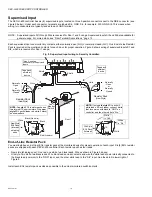
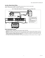
Relay outputs 3 and 4 are available for controlling an auxiliary device, such as a horn annunciator.
Figure 11 shows example wiring for controlling an output device.
Fig. 11. Relay output wiring from Security Controller to an auxiliary device.
Relay Output Wiring Notes
• Install the door strike or auxiliary output device per the vendor’s instructions.
• Use shielded, twisted-pair cabling to connect the circuit to the Security Controller. Maximum cable distance is 2000 feet
(610m)
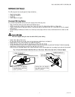
• Wire the door strike or auxiliary output device to the appropriate relay output on the Security Controller and to the power
supply used to power the strike or device. Each relay output on the Security Controller has a common terminal (C), and
normally open (NO) and normally closed (NC) terminal.
• At the Security Controller, ground shield wires to the designated grounding point at the enclosure. See Fig. 5 on page 13.
GN
D
DC
+
AX
3
AX
1
D1
AX2
D0
CAR
D
RE
AD
E
R
1
–
+
NC
2
NO
1
NC
1
NO
2
C1
C2
NC
3
NO
3
C3
NC
4
NO
4
C4
Shield
Security
Controller
Device
Power
Supply
(AC or DC,
24V max)
Current through SEC-H-600
relays must be limited to no
more than 3A to prevent board
damage.
If the power supply used does
not provide this current
limiting, install an external
fuse, as shown here.
Output
Device
Two 6-position connectors
for Relay Outputs

