

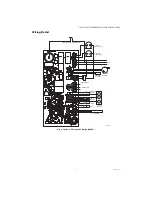

S9361A207X INTEGRATED BOILER CONTROLLERS
3
69-2751—05
14,000,485-016 1/4 in. (6.35 mm) diameter, 1-1/4 in.
(31.75 mm) length glass cartridge Fuse, 1 A,
Slow-Blow.
120650 Heat Conductive Compound.
Ignition Cables:
32004766-012—36-in. standard ignition cable (one
end with 90° boot, and other end with 1/4-in. quick
connect).
Use cable types recommended in Table 3.
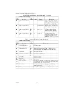
Table 3. Recommended Ignition Cables.
Transformer Requirement:
Add current ratings of module, pilot valve, main valve,
vent damper and any other components of the con-
trol system to determine transformer size require-
ment.
The AT150B1260—commonly used 50 VA transformer.
Approvals:
Varies with control model.
ANSI Z21.20 Automatic Gas Ignition Systems and
Components.
ANSI Z21.23 Gas Appliance Thermostats.
ANSI Z21.87: Automatic Gas Shutoff Devices for Hot
Water Supply Systems.
UL353 Limit Controls.
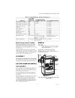
INSTALLATION
Automatic Ignition Control domestic and commercial
boiler systems are used on a wide variety of
equipment. Some of these applications may make
heavy demands on the controls, either because of
frequent cycling, or because of moisture, corrosive
chemicals, dust or excessive heat in the environment.
In these situations, special steps may be required to
prevent nuisance shutdowns and premature control
failures. These applications require Honeywell
Engineering review; contact your Honeywell Sales
Representative for assistance.
Frequent Cycling
These controls are designed for use on domestic and
commercial boiler systems that typically cycle less
than 10,000 cycles per year. In an application with
significantly greater cycling rates, we recommend
monthly checkout because the controls may wear out
more quickly.
Water or Steam Cleaning
Once a module or gas control has been wet, it may
operate unreliably and must be replaced. If the
appliance is likely to be cleaned with water or steam,
the controls and associated wiring should be covered
so that water or steam cannot reach them. The
controls should be high enough above the bottom of
the cabinet so they will not be subjected to flooding or
splashing during normal cleaning procedures. If
necessary, shield the controls to protect them from
splashing water. A NEMA 4 enclosure is
recommended.
High Humidity or Dripping Water
Over time, dripping water or high ambient humidity
can create unwanted electrical paths on the module
circuit board, causing the module to fail.
Never
install
an appliance where water can drip on the controls.
In addition, high ambient humidity can cause the
control to corrode and finally fail.
Where the appliance may be installed in a humid
atmosphere, make sure air circulation around the
module and gas control is adequate to prevent
condensation. It is also important to regularly check
out the system. A NEMA 4 enclosure may be needed.
Corrosive Chemicals
Corrosive chemicals can also attack the module and
gas control and eventually cause a failure. Where
chemicals may be used routinely for cleaning, make
sure the cleaning solution cannot reach the controls.
Where chemicals are likely to be suspended in the air,
as in some industrial and agricultural applications,
protect the module from exposure with a NEMA 4
enclosure.
Dust or Grease Accumulation
Heavy accumulation of dust or grease may cause the
controls to malfunction. Where dust or grease may be
a problem, provide covers for the module and gas
control that limit environmental contamination. A
NEMA 4 enclosure is recommended for the module.
Heat
The controls can be damaged by excessively high
temperatures. Make sure the maximum ambient
temperature at the control locations will not exceed
the rating of the control. If the appliance normally
operates at very high temperatures, insulation,
shielding, and air circulation may be necessary to
protect the controls. Proper insulation or shielding
should b provided by the appliance manufacturer;
make sure adequate air circulation is maintained
when the appliance is installed.
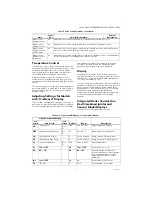
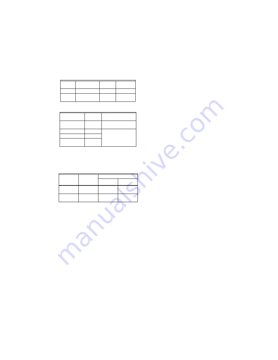
Table 1. Wells for Controller.
Part
Number
Spud Size
in. (mm)
Insertion
in. (mm)
Insulation
in. (mm)
123869A 1/2 (12.7) NPT 3 (76.2)
1-1/2 (38.1)
123870A 3/4 (19.05)
NPT
3 (76.2)
1-1/2 (38.1)
Table 2. Sensors for Controller.
Part Number
Length in.
(mm)
Application
50001464-001 12 (304.8) Well-mounted
controls
50001464-003 24 (609.6) Flush-mounted
controls
50001464-004 36 (914.4)
50001464-005 48
(1219.2)
Cable Type
Voltage
Rating
(rms)
Temperature Rating
°C
°F
UL Style
3217
10,000
150
302
UL Style
3257
10,000
250
484