


S9361A207X INTEGRATED BOILER CONTROLLERS
11
69-2751—05
Boiler Temperature Controller
When the water temperature reaches setpoint, the
controller ends the heating cycle. When the water
temperature drops below the setpoint minus the
differential, the control restarts a heat cycle to re-heat
the tank of water.
If the water temperature exceeds the max allowed
temperature, the control enters a manual reset lockout
state. For models that have reset capability, press any
on-board button (when present), cycle power, or use
the local (“rSt”) or remote display to reset.
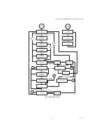
CHECKOUT
Put the system into operation and observe operation
through at least one complete cycle to make sure that
the controller operates properly. See Troubleshooting
section to assist in determining system operation.
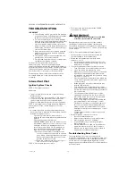
LOCATION AND MOUNTING
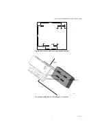
Sensing Bulb(s)
The boiler manufacturer usually provides a tapping for
the sensing bulb at a point where average water
temperature can be measured. See Fig. 5. Follow the
boiler manufacturer instructions.
The sensing bulb can be installed in an immersion
well. Wells and fittings must be ordered separately.
See 68-0040.
When an immersion well is used, the sensor should fit
snugly and should touch the bottom of the well for
best temperature response. Use heat-conductive
compound (Honeywell part no. 107408) to fill the
space between the bulb and the well to improve heat
transfer characteristics (optional). Make sure the
sensor is held firmly in the well.
WIRING
IMPORTANT:
For maximum trouble free operation, run the
sensor leadwires separately from any other
current-carrying wires.
All wiring must comply with local codes and
ordinances. Disconnect power supply before
beginning wiring. Connect according to water heater
manufacturer instructions.
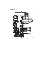
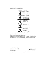
Fig. 5. Typical location of limit function sensor and
control module.
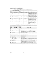
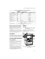
Table 8. 7-Segment LED Display - Adjustment Mode Options.
Parameter
3-Digit LED
Display Item
(1st Screen)
Remote Display (via
EnviraCOM connection)
Reset Card IQ Option Card
Adjust High Limit Setting
HL_
not editable
not editable
Adjust High Limit Differential
dF_
not editable
not editable
Pump Overrun Time (minutes)
Or_
yes
not editable
Pump Pre-purge Time
(minutes)
PP_
yes
not editable
Start Temperature
St_
yes
not editable
Priority Time
Pt_
yes
not editable
DH Terminal Function
dh_
yes
not editable
Reset Lockout
rSt
yes
not editable
Select degrees F or C Mode
F-C
not editable
not editable
Operating Setpoint
not available editable between the lower
High Limit range and
HL_
settings
editable between 32 °F and
Central Heat Setpoint
Operating Differential
not available editable between
dF_
and dF
range maximum
not editable
M27076
PILOT
MAIN
BURNER
INLET
INTEGRATED
BOILER
CONTROL
INDUCER
MOTOR
(OPTIONAL)
SUPPLY
PUMP
LIMIT
SENSOR