manualshive.com logo in svg
background image

R7824, R7847, R7848, R7849, R7851, R7852, R7861, R7886 AMPLIFIERS FOR 7800 SERIES AND R7140 RELAY MODULES

3

65-0109—14

Infrared:

R7848A,B for use with C7015 Infrared (lead sulfide)

Detector.

R7852A,B for use with C7915 Infrared (lead sulfide)

Detector.

Ultraviolet:

R7849A,B for use with C7027/C7035/C7044 Minipeeper 

Ultraviolet Detectors.

R7861A for use with C7061A Ultraviolet Detector.

R7886A for use with C7076A,D Ultraviolet Detectors with 

adjustable sensitivity.

Optical:

R7851B for use with C7927 and C7962 Flame Detectors.

R7851C for use with C7961E Flame Detectors.

NOTE: R7824C, Series 2 or greater and R7847C Series 4 or 

greater, pulse the shutter when signal of 1.5 Vac is 

sensed. Display readings of 0.7 to 2.4 Vdc are com-

mon.

Flame Failure Response Time: 

See Table 1.

Flame Signal (Volts dc):

Minimum Acceptable: 1.25 Vdc.

Flame Signal Voltage Range (displayed on Keyboard Display 

Module or measured with a 1M ohm/volt meter plugged into 

amplifier test jacks): 0.0 to 5.0 Vdc.

Environmental Ratings:

Ambient Temperature:

Operating: -40°F to 140°F (-40°C to 60°C).

Storage: -40°F to 150°F (-40°C to 65°C).

Humidity: Operating 85% rh continuous, noncondensing.

Vibration: Continuous 0.5G environment.

Weight: 

2.5 oz (71g), unpacked.

Dimensions: 

See Fig. 1.

SIL 3 Capable:

The Amplifiers R7847B,C, R7861A, R7886, R7851C or 

R7852B used with the appropriate flame detector and used in 

Relay Module EC7810A, 20A, 30A, 40L, 50A; 

RM7800[E,G,L,M], 30A, 38[A,B,C], 40[E,G,L,M] 50A, 

90[A,B,C,D], 97[A,C], 98A is SIL 3 Capable in a properly 

designed Safety Instrumented System. See form number 65-

0312 for Certificate Agreement.

Approvals:

Underwriters Laboratories Inc. Listed: File no. MP268, Guide 

no. MCCZZ: R7847A, R7847B, R7847C, R7861A, R7886A, 

R7848A, R7848B, R7849A, R7849B, R7851B, R7851C.

Underwriters Laboratories Inc. Component Recognized: File 

no. MP268, Guide no. MCCZZ: R7824C.

Canadian Standards Association Certified: LR95329-3.

Factory Mutual Approved: Report 1V9A0.AF. (R7851B, Report 

Number 3011020, June 16, 2003), R7851C (Report number 

3020842, April 12, 2005.)

SwissRe (formerly Industrial Risk Insurers) Acceptable.

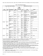
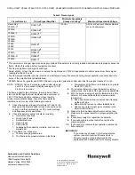
Table 1. Relay Module Flame Failure 

Response Time (FFRT).

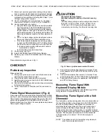
Fig. 1. Flame amplifier dimensions in in. (mm).

NOTE: EN298 Approved: When these amplifiers are used 

with an EC7810, EC7820, EC/RM7830, or 

EC/RM7850 Relay Module.

Accessories:

Flame Simulators:

Rectification: 123514A.

Ultraviolet: 203659.

Flame Detectors (ordered separately): select from Table 2.

Relay Module

Flame Failure Response 

Time (FFRT) in seconds

0.8 or 1 

2.0 or 3.0 

EC7810, EC7820, EC/RM7830, 

EC/RM7850

1.0

2.0

EC/RM7823, EC/RM7885, EC/

RM7890, RM7895, RM7896, 

RM7897, RM7898, RM7888, 

RM7838, RM7800, RM7840, 

R7140

0.8

3.0

RM7824

N/A

3.0

S

+

FLAME AMPLIFIER

3/8 (9)

3

(76)

M11460

3-9/16 (91)

7/8

(23)

Содержание R7824

Страница 1: ...40 Relay Modules The R7849A B Ultraviolet Flame Amplifiers are solid state plug in amplifiers that respond to an ultraviolet signal from a C7027 C7035 or C7044 Ultraviolet Flame Detector to indicate the presence of flame when used with 7800 SERIES and R7140 Relay Modules The R7851B Optical Flame Amplifiers are solid state plug in amplifiers that respond to optical signals from C7927 and C7962 Flam...

Страница 2: ...n the amplifier and relay module selected See Table 1 Plug in to 7800 SERIES and R7140 Relay Module through printed circuit board edge connector keyed for proper orientation Flame signal test jacks measure amplifier flame signal voltage 0 0 to 5 0 Vdc Flame signal strength reading range Color coded label identifies flame detection type Green rectification Red infrared Purple ultraviolet Blue pulse...

Страница 3: ...able The Amplifiers R7847B C R7861A R7886 R7851C or R7852B used with the appropriate flame detector and used in Relay Module EC7810A 20A 30A 40L 50A RM7800 E G L M 30A 38 A B C 40 E G L M 50A 90 A B C D 97 A C 98A is SIL 3 Capable in a properly designed Safety Instrumented System See form number 65 0312 for Certificate Agreement Approvals Underwriters Laboratories Inc Listed File no MP268 Guide no...

Страница 4: ... and R7847C Series 4 or greater pulse the shutter when signal of 1 5 Vdc is sensed Display readings of 0 7 to 2 4 Vdc are common i Order flame rod separately see flame detector Instructions for holder Plug in Flame Signal Amplifiers Applicable Flame Detectors Type Color Self Checking Model Flame Failure Response Time sec a Fuel Type Models Rectification Green Dymanic Self Check R7824Cb c h 3 Gas o...

Страница 5: ...Shock Hazard Can cause severe injury death or property damage Disconnect the power supply before beginning installation More than one power supply disconnection can be involved 1 Align the amplifier circuit board edge connector with the keyed receptacle on the 7800 SERIES and R7140 Relay Module Be sure the amplifier nameplate faces away from the Relay Module 2 Push in the amplifier until the circu...

Страница 6: ...AGE FLAME DETECTOR LEADS ARE COLOR CODED THE BLUE LEAD MUST BE CONNECTED TO THE F TERMINAL AND THE WHITE MUST BE CONNECTED TO THE G TERMINAL THE UV SENSING TUBE IS POLARITY SENSITIVE FLAME DETECTOR LEADS ARE COLOR CODED THE BLUE LEAD MUST BE CONNECTED TO THE F TERMINAL AND THE YELLOW MUST BE CONNECTED TO THE G TERMINAL THE UV SENSING TUBE IS POLARITY SENSITIVE CAUTION EQUIPMENT DAMAGE HAZARD INCOR...

Страница 7: ... amplifier and flame detector is used Flame Signal Measurement Fig 4 Flame signal can be measured at the Flame Signal Test Jacks see Fig 4 and at the Keyboard Display Module Measure the flame signal at the appropriate times defined in the Checkout section see applicable 7800 SERIES and R7140 Relay Module Instructions See Table 3 for acceptable and maximum flame signal voltage strengths CAUTION Equ...

Страница 8: ...t and the power supply is of the correct voltage and frequency and is sinusoidal 2 Check the detector wiring for defects including a Incorrect connections b Wrong type of wire c Deteriorated wire d Open circuits e Short circuits f Leakage paths caused by moisture soot or accu mulated dirt 3 For a flame rod make sure a There is enough ground area b The flame rod is properly located in the flame c T...

Отзывы: