background image

T7200D,E, T7300D,E,F AND Q7300 SERIES 2000 PROGRAMMABLE COMMERCIAL THERMOSTATS AND SUBBASES

63-4355—1

11

To advance to the next Installer Setup number, press the
Unoccupied Temp key.

To return to an Installer Setup number, press the Heat/
Cool Settings key.

To change a setting, use the increase

 ▲ 

 ▲ 

or

 ▼ 

 ▼ 

decrease

key.

To exit the Installer Setup, press the Run Program key.
The Installer Setup is automatically exited if no key
presses are made for four minutes.

NOTE:

Be sure to set the thermostat time after exiting the
Installer Setup.

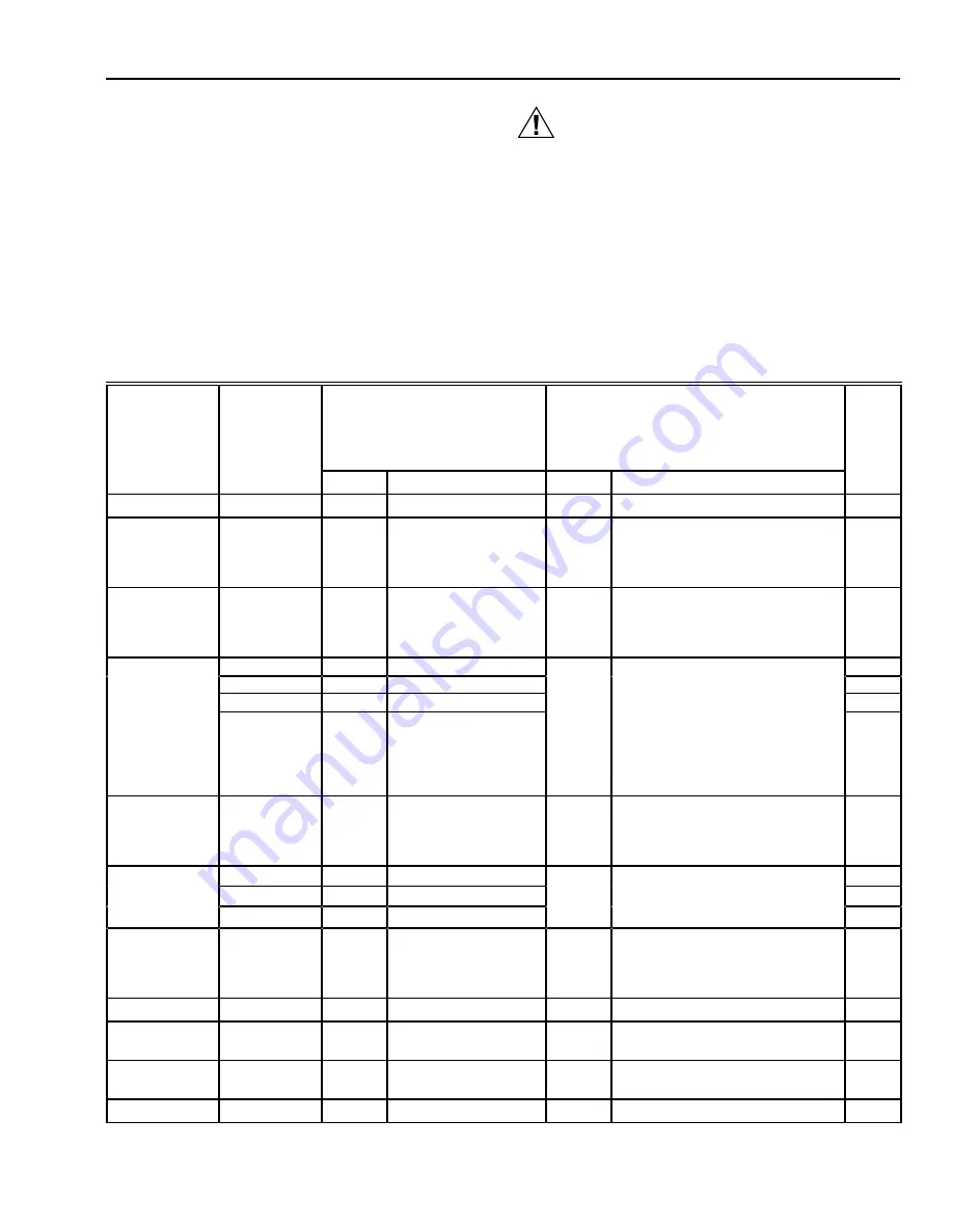
Installer Setup numbers are listed in Table 8.

CAUTION

Heat pump and electric heat systems must be
configured correctly in Installer Setup 2 to prevent
equipment damage caused by the system running
without the fan.

IMPORTANT

Only configurable numbers are shown on the device.
Example: If the thermostat does not have a system
key, Installer Setup number 12 will not be displayed.
Review Table 8 factory-settings and mark any
desired changes in the Actual Setting column. When
the Installer Setup is complete, review the settings to
confirm that they match the system.

Table 8. Thermostat Installer Setup Options.

Installer Setup

Number

(Press

Unoccupied

Temp key

Factory-Setting

Other Choices  

(Press 

 or 

 key to change)

Actual

Select

to change)

Display

Description

Display

Description

Setting

Not used

1

Fan operation

a

2

0

Conventional
applications where
equipment controls fan
operation in heat mode

1

Electric heat applications where
thermostat controls fan operation in
heat mode

Output stages of
heating

3

Depends

on

subbase

Stages of heat

0, 1, 2,  
or 3

0—No heating
1—One stage of heat
2—Two stages of heat
3—Three stages of heat

Heating cycle  

4

4

Stage 1—4 cph

3, 6, 8  

3—3 cph used for hot water systems  

rate

5

4

Stage 2—4 cph

or 9

or high efficiency furnaces

6

4

Stage 3—4 cph

6—6 cph used for conventional

7

4

Emergency heat relay  
is on continuously.
Highest stage of heat
cycles at 4 cph
(Q7300C or D only).

systems

8—8 cph used for conventional

systems

9—9 cph used for electric heat

systems  

Output stages  
of cooling

8

Depends

on

subbase

Stages of cooling

0, 1, 2  
or 3

0—No cooling
1—One stage of cool
2—Two stages of cool
3—Three stages of cool

Cooling cycle  

9

4

Stage 1—4 cph

3

3—3 cph  

rate

10

4

Stage 2—4 cph

11

4

Stage 3—4 cph

System setting
adjustment
(models with
System key)

12

Depends

on model

System selection

0, 1 or 2 0—System setting key is operational

1—Auto setting is disabled
2—Auto only setting

Not used

13

Degree tempera-
ture display

14

0

Temperature is
displayed in 

°

F

1

Temperature is displayed in 

°

C

Displaying
temperature  

15

0

Temperature is
displayed

1

Temperature is not displayed

Clock format  

16

0

12-hour clock format

1

24-hour clock format

(Continued)

a

Number 2 must be set to 1 to extend fan operation.

Содержание Q7300

Страница 1: ... Convenient overrides allow temporary setpoint changes Keypad lockout available T7200D E Thermostats Use on single stage conventional T7200D or heat pump T7200E applications T7300D E Thermostats Use on multistage conventional T7300D or heat pump T7300E applications Models available with remote sensor capability T7300F Thermostats Use on single stage or multistage system in conventional or heat pum...

Страница 2: ...n do not include normal manufacturing tolerances Therefore this unit might not exactly match the listed specifications This product is tested and calibrated under closely controlled conditions and some minor differences in performance can be expected if those conditions are changed T7200 T7300 Thermostats T7200 and T7300 Thermostats provide features listed in Table 1 Table 1 T7200 and T7300 Thermo...

Страница 3: ...and Cool factory setting 2 minutes option 0 minutes Minimum Off Cool and Heat Pump factory setting 4 minutes option 0 1 3 5 minutes Humidity Ratings 5 to 90 RH noncondensing Clock Accuracy 1 minute per month Finish Taupe color Dimensions See Fig 1 Mounting Means T7200 Thermostat mounts on a wallplate The T7300 Thermo stat mounts on a Q7300 Subbase The wallplate and subbase mount horizontally on a ...

Страница 4: ...et Program Occupied Temp Unoccupied Start Time Day System Fan Copy Occupied Start Time Run Program Temporary Occupied Continous Unoccupied Set Current Day Time Clear Start Time Unoccupied Temp Heat Cool Settings 1 3 8 35 6 3 4 172 3 1 4 82 1 7 8 47 4 3 4 121 4 1 8 105 1 16 2 7 5 16 186 5 127 4 5 8 117 1 11 16 43 7 8 22 9 16 14 M10234 1 T7200 WALLPLATE DOES NOT HAVE THE LED EXTENSION 1 1 ...

Страница 5: ...ERS YES NO NO NO M4823A Fig 2 Typical location of thermostat or remote mounted sensor Q7300 Subbase with Remote Mounted Temperature Sensor s If only the remote mounted temperature sensor s is used to sense and control room temperature then install the thermostat in an area that is accessible for setting and adjusting the temperature and settings If both the subbase and remote mounted temperature s...

Страница 6: ...ent for 3 wire The cable shield must be grounded only at the controlled equipment case Fig 4 Two T7047C Sensors and one T7047G Sensor providing temperature averaging network for T7300 Q7300 Thermostat Subbase Fig 5 Four T7047C Sensors providing temperature averaging network for T7300 Q7300 Thermostat Subbase Fig 6 Five T7047G Sensors providing temperature averaging network for T7300 Q7300 Thermost...

Страница 7: ...r terminal designations CAUTION Disconnect power before wiring to prevent electrical shock or equipment damage Table 6 Terminal Designations and Descriptions Standard Terminal Designations Alternate Terminal Designations Typical Connection Function Terminal Type A1 A2a Dry auxiliary contacts for economizer control A1 is normally open during Unoccupied periods and closed during Occupied periods Out...

Страница 8: ...LED common Annunciation Y1 C1 M Y Stage 1 compressor contactor Q7300C D Output 24V powered contact Y1 Y RS M Stage 1 cooling compressor Q7300A G L Output 24V powered contact Y2 C2 Stage 2 cooling compressor conventional Stage 2 compressor contactor heat pump Output 24V powered contact Y3 Stage 3 cooling compressor Output 24V powered contact BM ML7984 Actuator connection Q7300L only no call for hea...

Страница 9: ... equipment in Unoccupied periods Use the System and Fan keys to change the settings Fan and system operation are configured in the Installer Setup options The system settings are Em Heat T7200E T7300 Q7300C D Emergency heat relay is on continuously Thermostat cycles highest stage of heat Cooling system is off Compressor is de energized Heat Thermostat controls the heating Off Both the heating and ...

Страница 10: ...huFriSatSun Occupied 12 Override M4916 Aux Ht Em Ht Set Program Set Day Time Start Time Temporary Setting Enrg Em Heat M10227 MODE NUMBER DISPLAY COLUMN 2 OF TABLE 8 FACTORY SETTING OR OTHER CHOICE DISPLAY COLUMN 3 OR 5 OF TABLE 8 Fig 13 Display of Installer Setup number and setting Set Program Set Temperature Change Time Temp Occupied Temp Unoccupied Start Time Day System Fan Copy Occupied Start ...

Страница 11: ...iption Display Description Setting Not used 1 Fan operationa 2 0 Conventional applications where equipment controls fan operation in heat mode 1 Electric heat applications where thermostat controls fan operation in heat mode Output stages of heating 3 Depends on subbase Stages of heat 0 1 2 or 3 0 No heating 1 One stage of heat 2 Two stages of heat 3 Three stages of heat Heating cycle 4 4 Stage 1 ...

Страница 12: ...ing key is Auto only Remote sensing 22 0 Remote sensing not activated 1 Remote sensing activated Temperature averaging networkb 23 0 Temperature averaging disabled 1 Temperature averaging between local sensor and remote sensor s activated Not used 24 Keypad lockout level keypad lockout is enabled and disabled by DIP switch 1 on back of thermostat 25 0 No lockout 1 or 2 1 Lockout all keys on thermo...

Страница 13: ...oint can be set to Temperature range stops in cooling 35 45 Lowest setpoint cooling can be set to 46 to 99 Temperature range 1 F increments cooling setpoint can be set to Not used 36 Temperature display adjustment 37 0 No difference in displayed temperature and actual room temperature 1 thru 6 1 Display adjusts to 1 F higher than actual room temperature 2 Display adjusts to 2 F higher than actual ...

Страница 14: ...ogram Set Temperature Change Time Temp Occupied Temp Unoccupied Start Time Day System Fan Copy Occupied Start Time Run Program Temporary Occupied Continous Unoccupied Set Current Day Time Clear Start Time Unoccupied Temp Heat Cool Settings Auto System Fan Mon Room AM Occupied 1 Heat Run Program INSTALLER SYSTEM TEST Use the Installer System Test to check the thermostat configurations and operation...

Страница 15: ...mes on Q7300G only Stage one and stage two cool with system fan remain on 32 Stage three cool turns off 31 Stage two cool turns off 30 Stage one cool and system fan turn off Fan Equipment System Test Heat Cool Settings 40 Change from cooling to fan equipment system test 41 Fan comes on 42 High speed fan turns on Q7300L only 41 High speed fan turns off 40 Fan turns off Key Operation System Test Hea...

Страница 16: ...n the back of the thermostat activates the lockout features The switch must be set to the ON position up to activate the lockout feature See Fig 16 The factory setting is off down Remove the thermostat from the subbase and set the switch to ON if keypad lockout is desired The level of lockout is determined by the Installer Setup numbers 25 and 40 Fig 16 Setting the keypad lockout DIP switch 1 on t...

Страница 17: ...em Fan Copy Occupied Start Time Run Program Temporary Occupied Continous Unoccupied Set Current Day Time Clear Start Time Unoccupied Temp Heat Cool Settings Auto System Fan Mon Room AM Occupied 1 Heat Run Program Setting Program Times 1 Press Occupied Start Time NOTE Anytime a start time is not required press the Clear Start Time AM Mon Occupied 1 Set ProgramStart Time M4955A Set Program Set Tempe...

Страница 18: ...me Temp Occupied Temp Unoccupied Start Time Day System Fan Copy Occupied Start Time Run Program Temporary Occupied Continous Unoccupied Set Current Day Time Clear Start Time Unoccupied Temp Heat Cool Settings Day AM Occupied 1 Start Time Wed 3 Press Copy M4967A Set Program Set Temperature Change Time Temp Occupied Temp Unoccupied Start Time Day System Fan Copy Copy Occupied Start Time Run Program ...

Страница 19: ...ied Continous Unoccupied Set Current Day Time Clear Start Time Unoccupied Temp Heat Cool Settings Occupied Start Time 2 Press Day until the desired day is displayed AM Occupied 1 Set Program Start Time M4978A Mon Set Program Set Temperature Change Time Temp Occupied Temp Unoccupied Start Time Day System Fan Copy Occupied Start Time Run Program Temporary Occupied Continous Unoccupied Set Current Da...

Страница 20: ...cupied Temp Unoccupied Start Time Day System Fan Copy Occupied Start Time Run Program Temporary Occupied Continous Unoccupied Set Current Day Time Clear Start Time Unoccupied Temp Heat Cool Settings Auto System Fan Mon Room AM Occupied 1 Heat Run Program Changing Temperature Setpoint Until Next Program Period 1 Press increase or decrease key until the desired temperature is displayed NOTE If or ap...

Страница 21: ...stages Minimum on time is set in the installer setup number 32 Using the minimum on and off times assures that rapid cycling of equipment does not occur which extends equipment life Minimum on and off times are set in the Installer Setup T7200 T7300 Thermostat Operation Startup When power to the thermostat is turned on a startup and initialization program begins The startup occurs only on initial ...

Страница 22: ...cations O and B Terminals for Heating or Cooling Changeover The Q7300C controls heat pump changeover The Q7300D is only used in a heat pump application when the heat pump controls the reversing valve changeover See Table 13 for the operation of the O and B terminals on the Q7300C O and B Terminals on a Conventional Subbase Conventional subbase O and B terminals can be used to drive dampers and val...

Страница 23: ...or air to enter the building regardless of air suitability The situation can cause the heating or cooling to run more often than if suitable outdoor air is permitted to enter the building The thermostat can take advantage of an economizer by connecting the auxiliary relay contacts A1 and A2 of the subbase to control the economizer minimum position potentiometer The contacts close during the Occupi...

Страница 24: ...er The setpoint temperature range stops were configured Check Installer Setup number 34 and 35 and reconfigure the setpoint stops Keypad is locked When a locked key is pressed LOC will flash on the LCD Reset DIP switch 1 on back of thermostat to enable keypad Enter Installer Setup number 25 or 40 and reconfigure keypad lockout level Unable to configure Installer Setup Installer Setup is locked out...

Страница 25: ... to five minutes for the system to respond Enter Installer Setup number 33 Reconfigure minimum off time if required System selection is not set to Cool Set system selection to Cool System on indicator flame heat snowflake cool is Conventional heating equipment turns on the fan when the furnace has warmed up to a setpoint Wait a minute after seeing the on indicator and then check the registers disp...

Страница 26: ...300A2016 Q7300B1065 Two stage heat and two stage cool Snyder General part no 490249B 04 T7300F2010 Q7300A2016 Q7300B1073 Two stage heat and two stage cool Honeywell TRADELINE model T7300F2010 Q7300A2016 Wiring differences old new B X Q7300B1081 Two stage heat and two stage cool gray color T7300F2010 Q7300A2016 Q7300C Multistage heat pump subbase system switch AUTO COOL OFF HEAT EM HEAT fan switch ...

Страница 27: ...ary heat 3H 2C Honeywell TRADELINE model T7300F2010 Q7300D2002 Wiring differences old new B X X X1 Q7300D1079 Two stage heat pump with auxiliary heat 3H 2C gray color T7300F2010 Q7300D2002 Q7300D1087 Single stage heat pump with auxiliary heat 2H 1C gray color T7300F2010 Q7300D2002 Q7300E Multistage conventional subbase system switch none fan switch AUTO ON Q7300E1001 Two stage heat and two stage c...

Страница 28: ...ee subbase description for replacement information T7300A1062 Carrier logo part no HH07AX005 See subbase description for replacement information T7300A1070 Roca logo with international faceplate See subbase description for replacement information T7300A1088 Honeywell logo with Spanish faceplate See subbase description for replacement information T7300A1104 Honeywell logo Premier White color See su...

Страница 29: ...ences old new B X F X1 X2 E Y1 Y X4 to X field installed jumper required T8621A One stage heat and one stage cool conventional thermostat two transformer capability system switch HEAT AUTO COOL OFF fan switch ON AUTO T8621A7002 Honeywell logo TRADELINE model T7300D2007 Q7300A2008 Wiring differences old new C X T8621A7010 Honeywell logo Canadian TRADELINE model T7300D2007 Q7300A2008 Wiring differen...

Страница 30: ...TO T8621D7006 Honeywell logo TRADELINE model T7300D2007 Q7300A2008 Wiring differences old new C X T8621D7014 Honeywell logo Canadian TRADELINE model T7300D2007 Q7300A2008 Wiring differences old new C X T8621D7022 Honeywell logo TRADELINE model system switch HEAT OFF COOL dual fuel switch O and B terminals T7300D2007 Q7300A2057 Wiring differences old new C X T8621D7030 Trane logo part no THT 0607 o...

Страница 31: ...at and one stage cool heat pump thermostat Y7200B1009 Contains six T7200B1020 Thermostats Carrier part no 50QE90016101 T7200E2005 Wiring differences old new C X Y7300 Multistage T7300 thermostat and Q7300 subbase Y7300A1000 Contains one T7300A1047 Thermostat and one Q7300A1059 Subbase Micrometl part no 1060A 100 T7300F2002 Q7300A2016 Wiring differences old new B X Y7300A1018 Contains one T7300A106...

Страница 32: ...age heat pump with auxiliary heat 3H 2C TRADELINE model CHECK and FAIL LEDs taupe color Q7300C2020 Direct replacement for T8611M Thermostats Q7300D Multistage heat pump subbase used with T7300E or F Thermostat Q7300D2002 28 Two stage heat pump with auxiliary heat 3H 2C TRADELINE model remote sensor and discharge air sensor capability taupe color Q7300D2002 Q7300D2010 29 Single stage heat pump with...

Страница 33: ...mp thermostat used with Q7300C or D Subbase T7300E2020 Refer to subbase Honeywell logo TRADELINE model remote sensor capability system settings Em Heat Heat Off Cool Auto taupe color T7300E2020 Direct replacement for T8611M Thermostats T7300F Multistage thermostat for heat pump Q7300C or D Subbase and conventional Q7300A G or L Subbase applications T7300F2002 Refer to subbase Honeywell logo SUPER ...

Страница 34: ... 20 T7200E with one stage heat pump system Fig 21 Typical hookup of T7300D F Q7300A2008 in one stage heat and one stage cool conventional system with two transformers POWER SUPPLY PROVIDE DISCONNECT MEANS AND OVERLOAD PROTECTION AS REQUIRED JUMPER RC TERMINAL TO RH TERMINAL WHEN INSTALLED ON A SYSTEM WITH ONE TRANSFORMER CONNECT GND TO EARTH GROUND INSTALL FIELD JUMPER BETWEEN X4 AND X TO POWER LE...

Страница 35: ...PROTECTION AS REQUIRED JUMPER RC TERMINAL TO RH TERMINAL WHEN INSTALLED ON A SYSTEM WITH ONE TRANSFORMER 1 1 1 2 2 W2 L1 HOT L2 M10309 FAN RELAY Y1 G X SUBBASE RC HEAT RELAY 1 RH W1 L1 HOT L2 COMPRESSOR CONTACTOR 1 Y2 COMPRESSOR CONTACTOR 2 HEATING TRANSFORMER COOLING TRANSFORMER B O HEAT RELAY 2 COOL CHANGEOVER VALVE HEAT CHANGEOVER VALVE POWER SUPPLY PROVIDE DISCONNECT MEANS AND OVERLOAD PROTECT...

Страница 36: ...ORMER COOLING TRANSFORMER A2 A3 A1 X3 X1 X4 EQUIPMENT MONITOR 2 EQUIPMENT MONITOR 1 ECONOMIZER AS AS DISCHARGE AIR SENSOR HEAT RELAY 2 CONNECT GND TO EARTH GROUND INSTALL FIELD JUMPER BETWEEN X4 AND X TO POWER LEDS FROM SYSTEM TRANSFORMER USE ECONOMIZER INSTRUCTIONS FOR INSTALLATION DIRECTIONS DISCHARGE AIR SENSOR IS ONLY COMPATIBLE WITH T7300F THERMOSTAT POWER SUPPLY PROVIDE DISCONNECT MEANS AND ...

Страница 37: ...Y COOL CHANGEOVER VALVE EM MODE INSTALL FIELD JUMPER BETWEEN X4 AND X POWER LEDS FROM SYSTEM TRANSFORMER CONNECT GND TO EARTH GROUND JUMPER W2 TO Y2 FOR SECOND COMPRESSOR W3 IS AUXILIARY HEAT 5 C1 T T7147 REMOTE COMFORT ADJUST MODULE GND C2 C4 C3 C5 CA1 T CA2 CA4 CA3 CA5 T T POWER SUPPLY PROVIDE DISCONNECT MEANS AND OVERLOAD PROTECTION AS REQUIRED USE ECONOMIZER INSTRUCTIONS FOR INSTALLATION INSTR...

Страница 38: ... REMOTE COMFORT ADJUST MODULE GND W1 C2 COMPRESSOR CONTACTOR 1 C4 C3 C5 CA1 T CA2 CA4 CA3 CA5 T T Y2 COMPRESSOR CONTACTOR 2 TRANSFORMER W3 E HEAT RELAY 2 EM HT RELAY A2 A3 A1 X3 X1 X4 EQUIPMENT MONITOR 2 EQUIPMENT MONITOR 1 ECONOMIZER AS AS DISCHARGE AIR SENSOR HEAT RELAY 1 POWER SUPPLY PROVIDE DISCONNECT MEANS AND OVERLOAD PROTECTION AS REQUIRED USE A1 AND A2 WHEN THE CONTACTS SHOULD BE NORMALLY ...

Страница 39: ...UIPMENT MONITOR 2 EQUIPMENT MONITOR 1 ECONOMIZER AS AS DISCHARGE AIR SENSOR HEAT RELAY 1 CONNECT GND TO EARTH GROUND INSTALL FIELD JUMPER BETWEEN X4 AND X TO POWER LEDS FROM SYSTEM TRANSFORMER USE ECONOMIZER INSTRUCTIONS FOR INSTALLATION DIRECTIONS DISCHARGE AIR SENSOR IS ONLY COMPATIBLE WITH T7300F THERMOSTAT GH L1 HOT L2 POWER SUPPLY PROVIDE DISCONNECT MEANS AND OVERLOAD PROTECTION AS REQUIRED I...

Страница 40: ... and Building Control Honeywell Inc Honeywell Plaza P O Box 524 Minneapolis MN 55408 0524 Fig 32 T7300D F Q7300L2004 for single stage conventional heating systems with single stage cooling BM POWER SUPPLY PROVIDE DISCONNECT MEANS AND OVERLOAD PROTECTION AS REQUIRED REFER TO T7147 INSTRUCTIONS FOR TERMINAL CONNECTIONS T7047 HAS T T TERMINALS ONLY CONNECT GND TO EARTH GROUND JUMPER GH AND GL FOR SIN...

Отзывы: