background image

5

60-2150—10

L404A-D,F; L604A,L,M

INSTALLATION

Installation

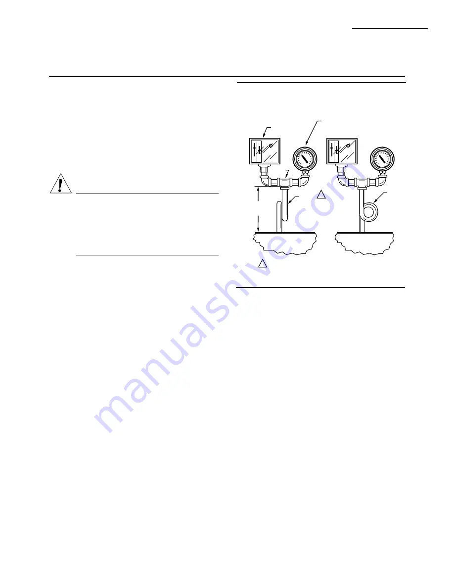
Fig. 2—Right and wrong mounting of a steam
trap (siphon loop), with approximate dimen-
sions in in. (mm).

4-1/2 TO 5-1/2

(114.3 TO 139.7)

BOILER

14026
STEAM TRAP
(SIPHON LOOP)

TEE

PRESSURE
GAUGE

PRESSUR
CONTROLLER

M8934

1

1

1/4 IN. BLACK IRON PIPE WITH 1/4 - 18 NPT EXTERNAL 
TRHEADS ON BOTH ENDS. BEND THE STEAM TRAP 
(SIPHON LOOP) TO LEVEL THE CONTROLLER.

CORRECT

BOILER

2-1/4 
(57.2) 
DIA.

INCORRECT

Make all pipe connections in accordance with approved

standards. Use only a small amount of pipe compound to
seal the connection joints. Excess pipe compound can clog
the small hole in the fitting and prevent the controller from
operating properly.

To avoid leaks and damage to the case, use a parallel jaw

wrench on the controller’s hexagonal fitting. Do not tighten
the controller by hand by holding the case.

Leveling

A controller with a mercury switch must be accurately

leveled for proper operation. It is level when the leveling
indicator  (Fig.  11)  hangs  freely  with  its  pointer  directly
over the index mark inside the back of the case. Level the
controller  by  carefully  bending  the  steam  trap  (siphon
loop).

Mounting Alongside a Pressure Gauge

To  mount  the  controller  alongside  a  pressure  gauge

(Fig. 2), remove the gauge. In its place, install a steam trap
(siphon  loop)  with  a  tee  on  top.  Using  elbows  and  pipe
nipples,  mount  the  controller  and  pressure  gauge  on  the
ends of the tee. Level the controller after installation.

WHEN INSTALLING THIS PRODUCT. . .

1. Read these instructions carefully. Failure to follow

them  could  damage  the  product  or  cause  a  hazardous
condition.

2. Check the ratings given in the instructions and on the

product  to  make  sure  the  product  is  suitable  for  your
application.

3. Installer must be a trained, experienced, flame safe-

guard control technician.

4.  After  installation  is  complete,  check  out  product

operation as provided in these instructions.

CAUTION

1. Disconnect power supply before beginning in-

stallation to prevent possible equipment dam-
age or electrical shock.

2. When  using  the  controller  with  a  compressor,

install a dampening device (such as a needle valve,
header, or surge tank) to dampen pulsations that
can damage the controller or reduce its life.

IMPORTANT:

1. Locate the controller where the ambient temperature

will not exceed 150

!

F (66

!

C).

2. Use pipe compound sparingly to avoid clogging the

hole in the pipe or diaphragm fitting.

3. Do not tighten the controller by hand by holding the case.
4. Accurately level the controller for proper operation.

LOCATION AND MOUNTING

NOTE: For most accurate operation; add supplemental heat

to installations where the temperature falls below minus
20

!

F (minus 29

!

C). Never locate the controller where the

temperature falls below minus 35

!

F (minus 37

!

C), be-

cause mercury in the switch freezes at this temperature.

When used with steam boilers, always mount the con-

troller  above  the  water  line  in  the  boiler.  A  steam  trap
(siphon loop) must always be connected between the con-
troller  and  the  boiler  (Fig.  2)  to  prevent  boiler  scale  and
corrosive vapors from attacking the diaphragm. The loop
on the steam trap must always be perpendicular to the face
of  the  controller.  If  the  loop  is  parallel  to  the  controller,
expansion or contraction of the loop tips the controller and
causes the switch to operate inaccurately.

The controller can be mounted (1) alongside the pres-

sure gauge, (2) in a fitting on the boiler provided by the
manufacturer, (3) at a remote location in case of excessive
vibration,  or  (4)  in  a  special  mounting  on  a  low  water
cutoff.

Содержание Pressuretrol L404 Series

Страница 1: ...or visible through cover Hexagonal fitting with 1 4 18 NPT internal threads for direct mounting to 14026 Steam Trap siphon loop Surface mount is available using screws through holes knockouts in case backing Can be used with steam air non combustible gases or fluids non corrosive to the pressure sensing ele ment Stainless steel diaphragm except 300 psi 21 1 kg cm2 2068 kPa models also allows use w...

Страница 2: ...troller case Scales are marked in psi and kPa ELECTRICALCONNECTIONS Internalscrewterminals hole in side of case for 1 2 in conduit MOUNTINGMEANS Hexagonalfittingondiaphragmhas 1 4 18 NPT internal threads for mounting on a pipe or steam trap siphon loop Also can be surface mounted using screws through two holes knockouts in back of case Ordering Information When purchasing replacement and moderniza...

Страница 3: ...ng Action on Pressure Rise Operating Rangesa Midscale Subtractive Differentiala Adjustable Maximum Surge Pressure Model to Setpoint psi kg cm2 kPa psi kg cm2 kPa psi kg cm2 kPa L404A spst breaks circuit 2 to 15b c 5 to 50 10 to 150b 20 to 300d 14 to 1 0 35 to 3 5 66 to 10 6 1 4 to 21 0 14 to 103 34 to 345 69 to 1034 138 to 2068 2 to 6 4 to 12 8 to 16 15 to 40 14 to 41 28 to 82 56 to 1 10 1 04 to 2...

Страница 4: ... 0 91 kg FINISH Gray APPROVALS Underwriters Laboratories Inc listed L404A B C D F L604A L M only file no MP466 vol 10 guide no MBPR CanadianStandardsAssociationcertified L404A B C D F L604A L only file no LR1620 guide no 400 E 0 REPLACEMENT PARTS 129178 Thermoplastic Cover 14026SteamTrap siphonloop 1 4in blackironpipe Necessary for boiler installations ACCESSORIES 33312B Knurled Adjustment Knob wi...

Страница 5: ...on the product to make sure the product is suitable for your application 3 Installer must be a trained experienced flame safe guard control technician 4 After installation is complete check out product operation as provided in these instructions CAUTION 1 Disconnect power supply before beginning in stallation to prevent possible equipment dam age or electrical shock 2 When using the controller wit...

Страница 6: ...ine voltage wiring 3 Fornormalinstallations usemoisture resistantNo 14 wire suitable for at least 167 F 75 C when you are using the controller with a flame safeguard primary control or at least 194 F 90 C when using it with a programming control 4 Forhightemperatureinstallations usemoisture resis tant No 14 wire selected for a temperature rating above the maximum operating temperature 5 Allmodelsh...

Страница 7: ...ON AS REQUIRED BREAKS R TO B AND MAKES R TO W WHEN PRESSURE RISES TO SETPOINT L2 POWER SUPPLY FLAME SAFEGUARD CONTROL MOTOR OR OTHER LOAD SPDT CONTROLLER HIGH LIMIT W R B ALARM Fig 9 L404F or L604 with jumper installed controlling an M644B motor M8940 L1 HOT L2 1 1 PROVIDE DISCONNECT MEANS AND OVERLOAD PROTECTION AS REQUIRED 24 VOLT THERMOSTAT LOW VOLTAGE RELAY L404 LOAD THERM POWER SUPPLY 1 2 Fig...

Страница 8: ... the main scale set point for the desired operating pressure by turning the main scale adjusting screw Fig 11 on the top of the case until the main scale setting indicator is at the desired value On an L404A B F with a 5 to 150 psi 3 to 10 3 kg cm2 34 to 1034 kPa operating range or an L604A adjust the differential setting by turning the dif ferential adjusting screw Fig 11 until the differential s...

Страница 9: ...ng on themodelofthecontroller AnL404AorCshouldbreak an L404BorDshouldmake anL404F L604L Mshouldbreak R B and make R W and an L604A should break R2 B and make R1 W If it makes the ohmmeter reads zero if it breaks the ohmmeter reads infinity 5 Raise the set point of the controller simulating a pressure decrease through a range greater than the differen tial The switch should break or make just the o...

Страница 10: ...e pointer may be over the index mark but the controller still may not be operating within the tolerance of its scale setting In this case carefully bend the steam trap siphon loop until the controller switches properly MAINTENANCE The cover of the controller should be in place at all times to protect the internal components from dirt dust and physical damage Routine maintenance should consist of o...

Страница 11: ...11 60 2150 10 ...

Страница 12: ... Home and Building Control Helping You Control Your World Honeywell Inc Honeywell Limited Honeywell Limitée 1985 Douglas Drive North 740 Ellesmere Road Golden Valley MN 55422 Scarborough Ontario M1P 2V9 Printed in U S A www honeywell com bbc ...

Отзывы: