


-- 2 --
462 06 1211 00
3/17/06
Important Information
This kit includes a Honeywell conversion kit for converting
Honeywell VR8200, VR8205S, SV9500, SV9501 or VR8204M
gas valves certified for use with Propane Gas (and so marked) to
units functionally the same as the certified furnace for use with
Natural Gas. If converting from propane gas to natural gas, the
gas valve conversion kit, main burner orifices, and pilot orifice, all
found in this kit, must be installed.
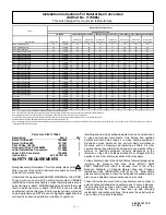
For converting the furnace from standard altitude on natural gas to
high altitude (2001 feet above sea level or greater) on natural gas,
the Honeywell conversion kit and pilot orifice changes are not
needed. Only the main burner orifices require changing. Refer to
Table 1
for proper orifice size for specific model number, input
capacity, and installation altitude.
The orifices provided in this kit are stamped to indicate the size
(twist drill number) and are sized for natural gas ONLY. Do NOT
use them with butane or a mixture of butane and propane. The
parts list specifies the size orifices supplied in the kit. Compare the
size marking on the orifices with the sizes as listed in the parts list.
Make sure you have the correct main burner orifices.
Extreme care is used to assure that this kit contains the proper
orifices.
Oversized orifices could result in hazardous
conditions, especially if the venting is inadequate.
For that
reason, we recommend that the installer check the size of the
orifice with a new twist drill of the correct size. This procedure
assures that the orifices provided are the correct size.
ELECTRIC SHOCK HAZARD/FIRE AND/OR
EXPLOSION HAZARD.
Failure to follow this warning could result in
equipment damage, personal injury, death
and/or property damage.
The gas supply shall be shut OFF prior to
disconnecting the electrical power, before
proceeding with the conversion.
Turn OFF electric power supply at disconnect
switch or service panel before starting
installation.
!
D
Shut off gas supply to furnace at manual shut--off valve be-
fore starting installation.
EXPLOSION HAZARD
Failure to follow this warning could result in
personal injury, death and/or property damage.
If unit is still running, allow 2.5 minutes after gas
shut off before turning off power, Shut Off electric
power at unit disconnect and service panel.
!
D
Disconnect electric power supply to the furnace before
starting installation.
D
Check for gas leaks after installation of kit and before at-
tempting to start furnace.
D
Locate the Natural Gas Conversion Label next to the fur-
nace rating plate.
D
Fill out and attach the Field Conversion Label to the front ex-
terior of the furnace.
FIRE,
EXPLOSION,
CARBON
MONOXIDE
POISONING HAZARD.
Failure to follow these instructions exactly could
result in personal injury, death and/or property
damage.
This conversion kit shall be installed by a
qualified service agency in accordance with the
manufacturer’s instructions and all applicable
codes and requirements of the authority having
jurisdiction.
If
the
information
in
these
instructions is not followed exactly, a fire, an
explosion or production of carbon monoxide may
result causing property damage, personal injury
or loss of life. The qualified service agency is
responsible for the proper installation of this kit.
The installation is not proper and complete until
the operation of the converted appliance is
checked as specified in the manufacturer’s
instructions supplied with the kit.
!
Gas Pressure
D
Refer to the furnace rating plate for the approved gas input
rating.
D
Gas input to burners MUST NOT exceed the rated input
shown on rating plate.
D
Do NOT
allow minimum gas supply pressure to vary down-
ward. Doing so will decrease input to furnace. Refer to
Table 2
for gas supply and manifold pressures.
Table 2
Gas Pressures
Gas
Supply Pressure
Manifold
Type
Recommended
Max.
Min.
Pressure
Natural
7
″
13
″
4.5
″
3.5
″
Installation
ELECTRIC SHOCK HAZARD/FIRE AND/OR
EXPLOSION HAZARD.
Failure to follow this warning could result in
property damage, equipment damage, personal
injury and/or death.
Turn OFF gas supply at manual gas valve
before turning OFF electric power supply and
starting installation.
Turn OFF electric power supply at disconnect
switch or service panel before starting
installation.
!


