background image

MODBUS-GW Installation and Operation Manual —

 P/N LS10015-000NF-E:C2  4/30/2019

19

Connections

Installation

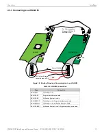
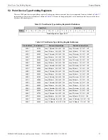
2.3.3  Connecting to an HS-NCM

Figure 2.8  Routing Power and Communication to an HS-NCM

Table 2.4  HS-NCM Connections

Type

Connection

HS-NCM-W 

Twisted pair wire

HS-NCM-SF 

Single mode fiber-optic cable

HS-NCM-MF 

Multimode fiber-optic cable

HS-NCM-WSF

Twisted pair wire, Single mode fiber-optic cable

HS-NCM-WMF

Twisted pair wire, Multimode fiber-optic cable

HS-NCM-MFSF

Multimode fiber-optic cable, Single mode fiber-optic cable

TB2

For Communications, 
Connect USB A to B 

OR

 USB B to A

MODBUS-GW

24V In From External 
Power Source to TB2

Out to HS-NCM

HS-NCM

24 VDC

+

+

Содержание Notifier MODBUS-GW

Страница 1: ...Modbus Gateway MODBUS GW Installation and Operation Manual Document LS10015 000NF E Rev C2 4 30 2019 ECN 19 0599 MODBUS GW Installation and Operation Manual ...

Страница 2: ...ector may not provide adequate warning of a fire Smoke detectors cannot be expected to provide adequate warning of fires caused by arson children playing with matches especially in bedrooms smoking in bed and violent explosions caused by escaping gas improper storage of flammable materials etc Heat detectors do not sense particles of combustion and alarm only when heat on their sensors increases a...

Страница 3: ...e enclosure When possible make all cable entries from the sides or rear Before making modifications verify that they will not interfere with battery transformer or printed circuit board location Do not tighten screw terminals more than 9 in lbs Over tighten ing may damage threads resulting in reduced terminal contact pressure and difficulty with screw terminal removal This system contains static s...

Страница 4: ...ave any comments or suggestions about our on line help or manuals please email us at FireSystems TechPubs honeywell com On Line Help Please include the following information Product name and version number if applicable Topic title The content you think should be corrected improved Detailed suggestions for correction improvement Documents Please include the following information Document part numb...

Страница 5: ... 2 1 3 Customer Supplied Equipment 14 2 2 Board Installation 15 Figure 2 1 NFS 320 Series Installation 15 Figure 2 2 NFS2 640 Series Installation 15 Figure 2 3 CHS 4L Installation 15 Figure 2 4 Securing the Board 15 2 3 Connections 16 2 3 1 Connecting the MODBUS GW 16 Figure 2 5 MODBUS GW Connections 16 Table 2 1 Connection Specifications 16 Figure 2 6 MODBUS GW LEDs 17 Table 2 2 LED Definitions 1...

Страница 6: ...uits Status Holding Registers 36 Table 5 9 Zones Panel Circuits Holding Register Bit Definitions 36 Table 5 10 Bell Circuit Holding Register Addresses 36 5 6 Bell Circuits Device Type Holding Registers 37 Table 5 11 Bell Circuits Device Type Holding Register Bit Definitions 37 Table 5 12 Bell Circuit Device Type Holding Register Addresses 37 5 7 Panel Status Holding Register 37 Table 5 13 Panel St...

Страница 7: ... Table D 1 Device Type Values Detectors 46 Table D 2 Device Type Values Monitor Modules 46 Table D 3 Device Type Values Control Modules 47 Appendix E System Troubles 48 Table E 1 System Troubles Register Map 48 Appendix F Conversion to Modbus RTU 58 F 1 Hardware Configuration 58 F 2 Software Configuration 58 Figure F 1 Connect a Configuration Computer 58 Table F 1 MGate MB3180 Configuration Settin...

Страница 8: ...re specified in the Cybersecurity Manual LS10217 000NF E 1 4 Required Software ChromeTM is required for use with the MODBUS GW 1 5 Environmental Requirements This product meets the following requirements for operation Temperature 0 C to 49 C 32 F 120 F Relative Humidity 93 2 non condensing at 32 2 C 90 3 F However it is recommended that this product be installed in an environment with a normal roo...

Страница 9: ... and response pair creates network traffic of 2632 bits per second 329 x 8 Therefore the network must be able to accommodate at least 0 0027 Mbps data flow Once every five seconds an analog request adds a small amount of network traffic Formula for MODBUS GW network bandwidth requirement based on polling rate Bandwidth Requirement 329 x 1000 polling rate in milliseconds x 8 106 Mbps Table 1 1 Modb...

Страница 10: ...t IP network connection is used with the architectures described in Figures 1 1 and 1 2 Figure 1 1 Single Panel Architecture Figure 1 2 NFN Network Architecture Modbus IP Client FACP NUP IP Network Ethernet Ethernet MODBUS GW FACP FACP IP Network MODBUS GW FACP Modbus IP Client HS NCM or NCM NFN Network Ethernet Ethernet Ethernet MODBUS GW Configuration Web Page ...

Страница 11: ...y which communicates with a Modbus client The second gateway must have a separate and unique IP address from the first gateway An example system is shown in Figure 1 3 Figure 1 3 Redundant Modbus Gateways FACP FACP NFN Network FACP IP Network Modbus Client MODBUS GW Configuration Web Page HS NCM OR NCM HS NCM OR NCM MODBUS GW MODBUS GW Ethernet Ethernet Ethernet Ethernet ...

Страница 12: ...neral Purpose Signaling Devices and Systems Second Edition UL 2572 Mass Notification Systems Second Edition Underwriters Laboratories Canada CAN ULC S527 11 Standard for Control Units for Fire Alarm Systems Third Edition CAN ULC S559 13 Standard for Equipment for Fire Signal Receiving Centres and Systems Second Edition Installation This product is intended to be installed in accordance with the fo...

Страница 13: ...30 and Later Software version 4 30 and later does not support EMPCA board types Only EMPCB board types are supported Table 1 3 Compatible Equipment Type Equipment Fire Panels NFS 320 NFS2 640 NFS2 3030 Network Cards NCM W NCM F HS NCM W HS NCM SF HS NCM MF HS NCM WSF HS NCM WMF HS NCM MFSF Gateways NFN GW EM 3 PC NFN Gateways NFN GW PC F NFN GW PC W NFN GW PC HNMF NFN GW PC HNSF NFN GW PC HNW Othe...

Страница 14: ... P N 75665 Used to connect the MODBUS GW board to an HS NCM board 2 1 2 Network Components High speed Network Communication Module HS NCM Used to facilitate network communication between the MODBUS GW and a high speed NFN network sold separately OR Network Communication Module NCM Used to facilitate network communication between the MODBUS GW and an NFN network sold separately OR Compatible FACP w...

Страница 15: ...ypad Removed Install bracket on 1 2 standoffs Place the board s tab in the bracket slot and screw the board to the top of the standoffs May be stacked in front of or behind another board using standoffs of adequate length to clear the rear board Mounting Studs Board Mount in 4th column of the NFS2 640 Series chassis Mount chassis to backbox before installing the board in rear position May be mount...

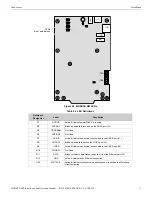
Страница 16: ...B 2 Locate in same cabinet or use close nipple fitting J2 USB A 2 Locate in same cabinet or use close nipple fitting J3 Ethernet 2 Line Impedance 100 ohm Max Distance 328 083 ft 100 m J4 NUP A 2 RS 232 Locate in same cabinet or use close nipple fitting All wiring from the power supply is power limited and a separation of at least 1 4 inch 6 35 mm must be maintained between power limited and non po...

Страница 17: ... Used D7 USB B Active Lit indicates a device is connected to the USB B port J1 D8 NUPA TX Blinks when data is sent on the NUP A port J4 D9 USB A Active Lit indicates a device is connected to the USB A port J2 D10 NUPB TX Not Used D11 DATA Blinks to indicate data transmission to or from the Ethernet port J3 D12 LINK Active Lit indicates an Ethernet connection D22 WDT FAIL Active Lit indicates the s...

Страница 18: ...ard NCM Figure 2 7 Routing Power and Communication to a Standard NCM Table 2 3 Standard NCM Connections Type Connection NCM W Twisted pair wire NCM F Fiber optic cable TB2 24V In From External Power Source to TB2 Out to NCM NCM MODBUS GW Connect Either Cable to Either NUP Connector on the NCM Communication from NUP A J4 Only 24 VDC ...

Страница 19: ...ction HS NCM W Twisted pair wire HS NCM SF Single mode fiber optic cable HS NCM MF Multimode fiber optic cable HS NCM WSF Twisted pair wire Single mode fiber optic cable HS NCM WMF Twisted pair wire Multimode fiber optic cable HS NCM MFSF Multimode fiber optic cable Single mode fiber optic cable TB2 For Communications Connect USB A to B OR USB B to A MODBUS GW 24V In From External Power Source to ...

Страница 20: ...n FACP 2 3 5 Connecting to the PNET 1 Surge Suppressor Figure 2 10 Connecting to the PNET 1 FACP From FACP NUP Connector NUP Cable Provides Both Power and Communication To NUP A J4 only Not Used MODBUS GW Panel is shown for illustrative purposes only The MODBUS GW is mounted within the FACP cabinet and connected with the NUP connection located on the FACP Ground J3 PNET 1 MODBUS GW ...

Страница 21: ...Power Installation 2 4 System Power 2 5 Testing and Maintenance Testing and maintenance should be performed according to the Testing and Maintenance section of NFPA 72 and CAN ULC S536 Table 2 5 Power Requirements Power Requirement Input Voltage Nominal 24 VDC Input Current 24 VDC 125 mA ...

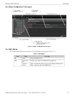
Страница 22: ... on resetting and reviewing the IP settings of the MODBUS GW 3 2 Configuring the MODBUS GW 3 2 1 Logging into the Web Page Log into the MODBUS GW as follows 1 Start the web browser 2 Navigate to the IP address of the gateway default http 192 168 1 2 3 If a security warning appears select the option to continue anyway Refer to 3 3 Security Certificate for more information 4 Log into the web page a ...

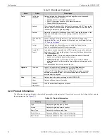
Страница 23: ...Enter or Change Text Navigation Tree Additional Properties see 3 2 5 Node List see 3 2 6 Click to View Sub items Main Menus see 3 2 3 Click for Product Information see 3 2 4 Click for Drop down List Click to Apply Changes Error Log Not Used Table 3 1 Main Menus Menu Option Description File Reboot Reboots the MODBUS GW View Refresh Node List Refreshes the node list in the MODBUS GW navigation tree ...

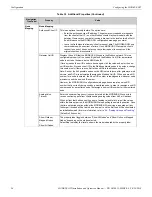
Страница 24: ...rol feature Note UL certification is voided if Control is enabled Create CSV Report Downloads a comma separated value CSV register map report in standard file format to the PC running the browser Hover over the label and select one of the following options With All Points The report contains information about all possible points on all configured panels on the network With Actual Points Recommende...

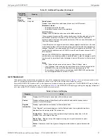
Страница 25: ...t and is not configurable NFN Settings General Information Connection Port Displays the type of connection port used Serial USB etc Connection Type Displays how the gateway is connected to the NFN NCM Version Displays the NCM version number Note This property does not appear when there is no NFN connection NCM Status Bits Displays the NCM status which can be Piezo UPS Failure Network Fail Port A N...

Страница 26: ... the 240 possible nodes on the NFN network except for gateways web servers and DVCs is automatically assigned a Modbus Unit ID When a new unit ID number for a node is entered the old unit ID number is reassigned to whichever node previously used the new unit ID number However the MODBUS GW configuration web page does accept a new unit ID number that is currently being used by a monitored node In o...

Страница 27: ...at was changed Example The node assigned Unit ID 214 is changed to be Unit ID 5 The result is that the node that was Unit ID 214 is now 5 and the node that was Unit ID 5 is now 214 However the MODBUS GW configuration web page does accept a new unit ID number that is currently being used by a monitored node In order to reassign a unit ID number used by a monitored node first assign a new unit ID nu...

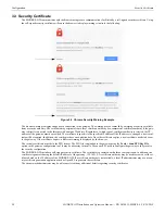
Страница 28: ... changed a new certif icate will be required In addition the certificates have an expiration date Once the certificate expires a new certificate needs to be sent to the gateway If the certificate expires a different warning is displayed by the browser The security certificate must be in the PFX format The PFX file is uploaded to the gateway using the Tools Send PFX Key File option in the gateway c...

Страница 29: ...bus Command Support 4 2 1 Modbus Commands The MODBUS GW supports the following Modbus commands Read Input Registers 0x04 Read Holding Registers 0x03 Write Single register 0x06 Read Device Identification supported 43 14 0x2B 0x0E 4 2 2 Exception Responses The MODBUS GW sends exception responses to its Modbus clients as appropriate e g invalid command invalid data etc For more information refer to A...

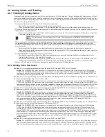
Страница 30: ...alog Value Time Out Use Case 2 A client requests analog values from the points L1M1 through L1M10 After 10 minutes of polling on a 10 second interval the client stops requesting analog values for these points Result The MODBUS GW sends back zeros in response to the first request for analog values from the points L1M1 through L1M10 The MODBUS GW sends back actual values on the second request from t...

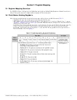
Страница 31: ...e Security Critical Process Medical Mass Notification or Supervisory alarm state If the point is not present in the panel programming all bits in the lower byte will contain a 1 or the value FFH The only possible active event type for zones is Non Fire Activation 71H See Appendix C Table 5 1 Point Status Holding Register Bit Definitions Upper Byte Lower Byte Bit No 15 14 13 12 11 10 9 8 7 6 5 4 3 ...

Страница 32: ...159 41201 41400 L4D1 L4D159 41401 41600 L4M1 L4M159 41601 41800 L5D1 L5D159 41801 42000 L5M1 L5M159 42001 42200 L6D1 L6D159 42201 42400 L6M1 L6M159 42401 42600 L7D1 L7D159 42601 42800 L7M1 L7M159 42801 43000 L8D1 L8D159 43001 43200 L8M1 L8M159 43201 43400 L9D1 L9D159 43401 43600 L9M1 L9M159 43601 43800 L10D1 L10D159 43801 44000 L10M1 L10M159 NOTES There are unused registers on every loop in order ...

Страница 33: ... 6 8 10 158 Loop 2 Module 1 3 5 9 11 159 44401 44500 Loop 3 Detector 2 4 6 8 10 158 Loop 3 Detector 1 3 5 9 11 159 44501 44600 Loop 3 Module 2 4 6 8 10 158 Loop 3 Module 1 3 5 9 11 159 44601 44700 Loop 4 Detector 2 4 6 8 10 158 Loop 4 Detector 1 3 5 9 11 159 44701 44800 Loop 4 Module 2 4 6 8 10 158 Loop 4 Module 1 3 5 9 11 159 44801 44900 Loop 5 Detector 2 4 6 8 10 158 Loop 5 Detector 1 3 5 9 11 1...

Страница 34: ... 1 or the value FFH The holding register addresses and the zones contained in these addresses are detailed in Table 5 6 Table 5 5 Zones Panel Circuits Holding Register Bit Definitions Upper Byte Lower Byte Bit No 15 14 13 12 11 10 9 8 7 6 5 4 3 2 1 0 Bit Name Ack Block Prealarm Trouble InActive Active Enable Disable Ack Fire Alarm Active Event Type When Bit 11 is set to 1 see Appendix C When indiv...

Страница 35: ...ints by fire panel is described in Table 5 8 Register Address Panel Circuits 49111 49118 P1 1 P1 8 49119 49126 P2 1 P2 8 49127 49134 P3 1 P3 8 49135 49142 P4 1 P4 8 49143 49150 P5 1 P5 8 49151 49158 P6 1 P6 8 49159 49166 P7 1 P7 8 49167 49174 P8 1 P8 8 49175 49182 P9 1 P9 8 49183 49190 P10 1 P10 8 49191 49198 P11 1 P11 8 49199 49206 P12 1 P12 8 Table 5 8 Supported Circuits by Panel Panel Max Panel...

Страница 36: ... the lower byte will contain a 1 or the value FFH The holding register address and the bell circuit contained in the address is detailed in Table 5 10 Table 5 9 Zones Panel Circuits Holding Register Bit Definitions Upper Byte Lower Byte Bit No 15 14 13 12 11 10 9 8 7 6 5 4 3 2 1 0 Bit Name Ack Block Prealarm Trouble InActive Active Enable Disable Ack Fire Alarm Active Event Type When Bit 11 is set...

Страница 37: ...Table 5 14 Silence The fire alarm control panel is silenced when this bit is set to 1 Reset Not used Table 5 11 Bell Circuits Device Type Holding Register Bit Definitions Upper Byte Lower Byte Bit No 15 14 13 12 11 10 9 8 7 6 5 4 3 2 1 0 Device Types see Appendix D Table 5 12 Bell Circuit Device Type Holding Register Addresses Start Address End Address Device Address Device Address 49410 49410 Bel...

Страница 38: ...hown in Table 5 16 A single bit is reserved for each trouble in the system The assignment of bits to trouble codes is shown in Appendix E System Troubles Table 5 15 Input Register Analog Values Start Address End Address Analog Value 16 bits 30001 30200 L1M1 L1M159 30201 30400 L2M1 L2M159 30401 30600 L3M1 L3M159 30601 30800 L4M1 L4M159 30801 31000 L5M1 L5M159 31001 31200 L6M1 L6M159 31201 31400 L7M...

Страница 39: ...des an example of how this is represented in a register NOTE Information debug values are used by the MODBUS GW Unit ID only All other nodes reject reads in this address range Table 5 17 Gateway Information Input Register Addresses Start Address End Address Description 35100 35500 Information Debug information 35100 35115 Node Status 1 On Line 0 Off Line The MODBUS GW tracks the node status of all...

Страница 40: ...reading the identification and additional information about the MODBUS GW as shown in Table 5 19 Table 5 19 43 14 0x2B 0x0E Read Device Identification Object ID Object Name Description Value 0x00 VendorName Notifier 0x01 ProductCode 1 0x02 MajorMinorRevision V1 0 Example 0x03 VendorUrl www notifier com 0x04 ProductName Modbus Gateway 0x05 ModelName Modbus Gateway 0x06 UserApplicationName Modbus Ga...

Страница 41: ...t was used during development to test the gateway It is designed primarily as a testing device for verification of correct protocol operation in new or existing systems 6 4 How do I recover a lost password from the gateway If the password for the gateway is lost programming changes cannot be made In this situation the gateway settings must be reset Refer to Appendix A Gateway Settings for instruct...

Страница 42: ...of the points As long as the client makes analog reads of the same points faster than the Analog Value Polling Time then the gateway will continue to poll these points If the cli ent polls slower than the Analog Value Polling Time then the gateway may return readings of zero because this will be considered an ini tialization read 6 10 System Trouble For information about system trouble information...

Страница 43: ...ash drive to a PC and create a file named default ldc The contents of the file is not significant however ensure that the file does not have an additional hidden file extension This file will be automatically deleted from the flash drive by the gateway 2 Eject the flash drive from the PC 3 Disconnect power from the gateway 4 Disconnect the communication cable to the gateway USB port if present and...

Страница 44: ...ported by the MODBUS GW or the FACP A Control command was sent to the gateway Contact customer service Illegal function 0x02 Register address range specified by the client is not supported by the FACP Register address range requested is valid but the device e g Detector Module Zone etc is not present in the specified FACP Analog Value is requested from a register which is not associated with a 4 2...

Страница 45: ...25H Supervisory Signal Guard s Tour 30H Supervisory Signal Equipment 40H Mass Notification Supervisory Low Priority 45H Disabled Alarm AFP2800 Panel Only 52H Disabled Active AFP2800 Panel Only 55H Non Fire Activation 71H Non Fire Activation no acknowledgment required 72H CO Alarm Fire Alarm EAH CO Supervisory EBH CO Supervisory Photo Supervisory ECH CO Supervisory Fire Alarm EDH CO Alarm Photo Sup...

Страница 46: ...OR 53 PAS INHIBIT 81 PULL STATION 54 POWER MONITR 82 RF MON MODUL 55 PROCESS MON 83 RF PULL STA 56 PROCESS AUTO 84 SMOKE CONVEN 57 RESET SWITCH 85 SMOKE DETECT 58 SIL SWITCH 86 WATERFLOW 59 TELE PAGE 87 WATERFLOW S 60 TORNADO ALRT 88 ACCESS MONTR 61 TROUBLE MON 89 AREA MONITOR 62 ABORT SWITCH 90 AUDIO SYSTEM 63 MAN RELEASE 91 EQUIP MONITR 64 MANREL DELAY 92 HOLD UP 65 SECOND SHOT 93 RF SUPERVSRY 6...

Страница 47: ...S 171 HORN CIRCUIT 155 GEN TROUBLE 172 AUDIBLE CKT 156 GENERAL PEND 173 SPEAKER 157 TROUBLE PEND 174 REL END BELL 158 FORM C RESET 175 blank 159 ISOLATED SPK 176 RELEASE CKT 160 ISOLATED NAC 177 REL CKT ULC 161 RELAY FDBACK 178 RELEA FORM C 162 REL FORM C FB 179 REL AUDIBLE 163 MASS NOTIFICATION GENERAL 180 NONRESET CTL 164 MASS NOTIFICATION CONTROL 181 TELEPHONE 165 MASS NOTIFICATION STROBE 182 R...

Страница 48: ...ANNUN 9 TROUBLE 35003 0 ANNUN 9 NO ANSWER 8 ANNUN 13 NO ANSWER 1 ANNUN 10 TROUBLE 9 ANNUN 14 TROUBLE 2 ANNUN 10 NO ANSWER 10 ANNUN 14 NO ANSWER 3 ANNUN 11 TROUBLE 11 ANNUN 15 TROUBLE 4 ANNUN 11 NO ANSWER 12 ANNUN 15 NO ANSWER 5 ANNUN 12 TROUBLE 13 ANNUN 16 TROUBLE 6 ANNUN 12 NO ANSWER 14 ANNUN 16 NO ANSWER 7 ANNUN 13 TROUBLE 15 ANNUN 17 TROUBLE 35004 0 ANNUN 17 NO ANSWER 8 ANNUN 21 NO ANSWER 1 ANN...

Страница 49: ...NUN 34 NO ANSWER 11 ANNUN 38 NO ANSWER 4 ANNUN 35 TROUBLE 12 ANNUN 39 TROUBLE 5 ANNUN 35 NO ANSWER 13 ANNUN 39 NO ANSWER 6 ANNUN 36 TROUBLE 14 ANNUN 40 TROUBLE 7 ANNUN 36 NO ANSWER 15 ANNUN 40 NO ANSWER 35009 0 ANNUN 41 TROUBLE 8 ANNUN 45 TROUBLE 1 ANNUN 41 NO ANSWER 9 ANNUN 45 NO ANSWER 2 ANNUN 42 TROUBLE 10 ANNUN 46 TROUBLE 3 ANNUN 42 NO ANSWER 11 ANNUN 46 NO ANSWER 4 ANNUN 43 TROUBLE 12 ANNUN 4...

Страница 50: ...PERVISORY 3 STYLE 6 POS LOOP 6 11 PRINT QUEUE FULL 4 STYLE 6 POS LOOP 7 12 MEMORY LOSS 5 STYLE 6 POS LOOP 8 13 PRINTER COVER OPEN 6 STYLE 6 POS LOOP 9 14 PRINTER PAPER OUT 7 STYLE 6 POS LOOP 10 15 PRINTER OFF LINE 35014 0 Workstation Fan Failure 8 STYLE 4 SHORT A LOOP 3 1 UPS Failure 9 STYLE 4 SHORT B LOOP 3 2 MANUAL MODE ENTERED 10 STYLE 4 SHORT A LOOP 4 3 NCM COMM LOSS 11 STYLE 4 SHORT B LOOP 4 ...

Страница 51: ...7 NO ANSWER 2 ANNUN 74 TROUBLE 10 ANNUN 78 TROUBLE 3 ANNUN 74 NO ANSWER 11 ANNUN 78 NO ANSWER 4 ANNUN 75 TROUBLE 12 ANNUN 79 TROUBLE 5 ANNUN 75 NO ANSWER 13 ANNUN 79 NO ANSWER 6 ANNUN 76 TROUBLE 14 ANNUN 80 TROUBLE 7 ANNUN 76 NO ANSWER 15 ANNUN 80 NO ANSWER 35019 0 ANNUN 81 TROUBLE 8 ANNUN 85 TROUBLE 1 ANNUN 81 NO ANSWER 9 ANNUN 85 NO ANSWER 2 ANNUN 82 TROUBLE 10 ANNUN 86 TROUBLE 3 ANNUN 82 NO ANS...

Страница 52: ...14 NO ANSWER 11 ANNUN 118 NO ANSWER 4 ANNUN 115 TROUBLE 12 ANNUN 119 TROUBLE 5 ANNUN 115 NO ANSWER 13 ANNUN 119 NO ANSWER 6 ANNUN 116 TROUBLE 14 ANNUN 120 TROUBLE 7 ANNUN 116 NO ANSWER 15 ANNUN 120 NO ANSWER 35024 0 ANNUN 121 TROUBLE 8 ANNUN 125 TROUBLE 1 ANNUN 121 NO ANSWER 9 ANNUN 125 NO ANSWER 2 ANNUN 122 TROUBLE 10 ANNUN 126 TROUBLE 3 ANNUN 122 NO ANSWER 11 ANNUN 126 NO ANSWER 4 ANNUN 123 TROU...

Страница 53: ...O ANSWER 6 REMOTE DISPLAY 20 TROUBLE 14 REMOTE DISPLAY 24 TROUBLE 7 REMOTE DISPLAY 20 NO ANSWER 15 REMOTE DISPLAY 24 NO ANSWER 35028 0 REMOTE DISPLAY 25 TROUBLE 8 REMOTE DISPLAY 29 TROUBLE 1 REMOTE DISPLAY 25 NO ANSWER 9 REMOTE DISPLAY 29 NO ANSWER 2 REMOTE DISPLAY 26 TROUBLE 10 REMOTE DISPLAY 30 TROUBLE 3 REMOTE DISPLAY 26 NO ANSWER 11 REMOTE DISPLAY 30 NO ANSWER 4 REMOTE DISPLAY 27 TROUBLE 12 RE...

Страница 54: ...N LOOP 4 6 LOOP CONTINUITY TEST FAIL LOOP 7 14 UNPROGRAMMED DEVICE ON LOOP 5 7 LOOP CONTINUITY TEST FAIL LOOP 8 15 UNPROGRAMMED DEVICE ON LOOP 6 35034 0 UNPROGRAMMED DEVICE ON LOOP 7 8 IR ENABLED ON LOOP 5 1 UNPROGRAMMED DEVICE ON LOOP 8 9 IR ENABLED ON LOOP 6 2 UNPROGRAMMED DEVICE ON LOOP 9 10 IR ENABLED ON LOOP 7 3 UNPROGRAMMED DEVICE ON LOOP 10 11 IR ENABLED ON LOOP 8 4 IR ENABLED ON LOOP 1 12 ...

Страница 55: ...ISION 35038 0 DAL ADDRESS CONFLICT 8 MAPPING IN PROGRESS LOOP 7 1 DEVICE SERVICING REQUIRED 9 MAPPING IN PROGRESS LOOP 8 2 MAPPING IN PROGRESS LOOP 1 10 MAPPING IN PROGRESS LOOP 9 3 MAPPING IN PROGRESS LOOP 2 11 MAPPING IN PROGRESS LOOP 10 4 MAPPING IN PROGRESS LOOP 3 12 DATABASE CORRUPTED 5 MAPPING IN PROGRESS LOOP 4 13 AUDIO LIBRARY CORRUPTED 6 MAPPING IN PROGRESS LOOP 5 14 DATABASE INCOMPATIBLE...

Страница 56: ...d 7 Reserved 15 Reserved 35043 0 Reserved 8 Reserved 1 Reserved 9 Reserved 2 Reserved 10 Reserved 3 Reserved 11 Reserved 4 Reserved 12 Reserved 5 Reserved 13 Reserved 6 Reserved 14 Reserved 7 Reserved 15 Reserved 35044 0 Reserved 8 Reserved 1 Reserved 9 Reserved 2 Reserved 10 Reserved 3 Reserved 11 Reserved 4 Reserved 12 Reserved 5 Reserved 13 Reserved 6 Reserved 14 Reserved 7 Reserved 15 Reserved...

Страница 57: ...d 15 Reserved 35047 0 Reserved 8 Reserved 1 Reserved 9 Reserved 2 Reserved 10 Reserved 3 Reserved 11 Reserved 4 Reserved 12 Reserved 5 Reserved 13 Reserved 6 Reserved 14 Reserved 7 Reserved 15 Reserved 35048 0 Reserved 8 Reserved 1 Reserved 9 Reserved 2 Reserved 10 Reserved 3 Reserved 11 Reserved 4 Reserved 12 Reserved 5 Reserved 13 Reserved 6 Reserved 14 Reserved 7 Reserved 15 Reserved Table E 1 ...

Страница 58: ...tup_Verx x_Build_xxxxxxxx exe found on the Software CD shipped with the MGate MB3180 3 Once the software has been installed run MGate Manager 4 Power up the MB3180 Make sure the Ready and Ethernet lights are on 5 Configure the MB3180 for the network The settings specified in Table F 1 are required Settings not specified should be tailored to your network requirements Refer to the MGate MB3000 Modb...

Страница 59: ...S GW Figures F 2 and F 3 show possible configurations for connecting the MODBUS GW to the Moxa interface 3 Power up the system Figure F 2 Connection Through Crossover Ethernet Cable Figure F 3 Connection Through a Router NOTE The configuration used must have the approval of the AHJ Authority Having Jurisdiction FACP FACP NFN Network FACP MODBUS GW NCM USB MB3180 Crossover Ethernet Cable Modbus RTU...

Страница 60: ...ES AND DISCLAIMS ANY AND ALL OTHER WARRANTIES EITHER EXPRESSED OR IMPLIED WITH RESPECT TO THE PRODUCTS TRADEMARKS PROGRAMS AND SERVICES RENDERED BY MANUFACTURER INCLUDING WITHOUT LIMITATION INFRINGEMENT TITLE MERCHANTABILITY OR FITNESS FOR ANY PARTICULAR PURPOSE MANUFACTURER SHALL NOT BE LIABLE FOR ANY PERSONAL INJURY OR DEATH WHICH MAY ARISE IN THE COURSE OF OR AS A RESULT OF PERSONAL COMMERCIAL ...

Страница 61: ...NOTIFIER 12 Clintonville Road Northford CT 06472 1610 USA 203 484 7161 www notifier com ...

Отзывы: