background image

 AND ADJUSTMENT PROCEDURES FOR HONEYWELL 


MP-953F PNEUMATIC.OPERATORS USED ON ARMSTRONG HUMIDIFIERS

VIII.OPERATING RANGE AND START POINT

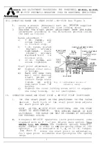
 MP-953B (See Figure 3)

Using a wrench (Honeywell Part No. 

 supplied

with gradutrol), loosen the cover locking screw.

2.

Unscrew the start point adjustment knob and make
adjustments according to the directions printed inside

IX.

the knob as follows:

Range adjustment 
a)

3 lb.

range,

all

screws backed

off

to friction stop.

b)

5 lb. range, plated

(outer)

s c r e w s

tightened.

Black

(inner)

s c r e w s

b a c k e d - o f f   t o

friction stop.

c)

10 lb.

range, all

screws tightened.

Start point adjustment 

Tighten cover until

it bottoms.

Back off (one turn
max.) until desired
start

point of

correct range scale
lines up

with

indicator near


marking.
Tighten the cover locking screw until it engages

the relay housing.

Do not overtighten.

OPERATING

1.

Set

S

TART POINT

COVER

RANGE ADJUSTMENT

LOCKING

/ S

C R E W

SCREWS

RANGE ADJUSTMENT


SCREWS

 BODY

Fig. 3 

Adjustment Points of
Gradutrol Relay.

START

RANGE AND START POINT

 MP-953F PILOT POSITIONER

the start point on the positioner to the value

desired.

Each click of the start point knob adjusts

the start point 

 psi.

NOTE:

ON THE MP-953F PILOT POSITIONER, ONLY THE START

POINT IS ADJUSTABLE.

THE SPRING RANGE IS NOT

ADJUSTABLE.

THE RANGE CAN ONLY BE CHANGED BY REPLACING

THE FEEDBACK SPRING.

Honeywell MP-953F operators (with positioners) come
standard with an 8 

13 psi (black) main spring. This

 does 


 The feedback spring, however,

maybe changed in order to 

vary 

the 

spring range of the

operator.

It is available in 3

(See Chart 4)

 or 10 lb. ranges.

Since the start point is adjustable,

full open point willbethe startpointplus the spring

range.

6

Содержание MP953B

Страница 1: ...the operator from the bonnet installing the operator on the bonnet replacing steam seals changing operator springs replacing the diaphragm replacing the rolling seal and replacing the valve and seat I REMOVING THE PNEUMATIC OPERATOR Many repair procedures require that the operator be removed from the bonnet assembly To remove the operator perform the following steps Refer to Figure 1 see back cove...

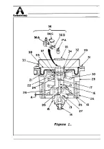
Страница 2: ...36 36 34 3g 23 37 Ad y p L _ 33 I 14 ...

Страница 3: ... groove of the stem adapter 17A b Place the spring 36C on top of the stem adapter 17A and bearing 36B with the longer tabs pointed downward toward the notches in the sides of the bearing c Slide the yoke 36A over the spring 36C bearing 36B and stem adapter 17A until the short tabs of the spring snap into place on both sides of the yoke Center the yoke over the stem 16 l Place the operator over the...

Страница 4: ...th spring showing should be toward the valve Carefully guide the seals into place in the bonnet 15 Slide the packing gland 18 over the stem and turn it into the bonnet Tighten the packing gland securely Turn the bonnet assembly 15 into the humidifier cap and tighten securely Install the pneumatic operator in accordance with Section II IV CHANGING OPERATOR SPRlNGS 1 2 3 4 5 6 7 a 9 10 Remove the pn...

Страница 5: ... 8 Remove the pneumatic operator in accordance with Section I Perform Section IV CHANGING OPERATOR SPRINGS steps 2 through 8 to disassemble the operator With the operator in the upright position remove the three screws 23 and ring 39 that secure the rolling seal 22 Remove the rolling seal 22 Then separate the cup 37 from the old seal Place the cup 37 into the new rolling seal Install the new seal ...

Страница 6: ...Generally the diaphragm is replaced without removing the operator from the humidirier However there are times that the location of the humidifier makes it more convenient to remove the operator to a workbench for repair Remove the six cover screws 31 from the operator cover 33 Lift the cover 33 from the frame 29 Remove the hex nut 34 and washer 32 from the support 24 Do not disturb the yoke assemb...

Страница 7: ... Tighten the cover locking screw until it engages the relay housing Do not overtighten OPERATING 1 Set 2 S c TART POINT iDJUSTMENT COVER RANGE ADJUSTMENT r nn LOCKING hlY D SC R E W SCREWS RANGE ADJUSTMENT BLANK 3 SCREWS RELA BODY Fig 3 Adjustment Points of Gradutrol Relay START 3R RANGE AND START POINT MP 953F PILOT POSITIONER the start point on the positioner to the value desired Each click of t...

Страница 8: ... Replace the bias spring located on top of the operator e Replace the pilot positioner f Turn on the instrument air ADJUSTMENT CHECK MP 953B AND MP 953F MODELS ONLY 1 Install guages in the main and pilot air lines 2 Main air pressure should be equal to or more than top of sequencing range 13 psi is minimum main pressure for device to function 3 Slowly apply pilot pressure and note the pressure at ...

Отзывы: