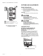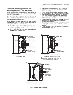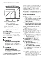
SERIES 71, 72, AND 76 MODUTROL IV™ MOTORS
7
63-2640—07
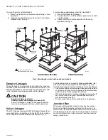
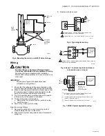
Fig. 4. Mounting the motor on a Q5001 Valve Linkage.
Wiring
CAUTION
Electrical Shock or Equipment Damage Hazard.
Can shock individuals or short equipment circuitry.
Disconnect all power supplies before installation.
Motors with auxiliary switches can have more than one
disconnect.
IMPORTANT
All wiring must agree with applicable codes,
ordinances and regulations.
1.
Ensure that the voltage and frequency stamped on the
motor correspond with the power supply characteristics.
2.
When connecting several motors in parallel, ensure that
the power supply VA rating is large enough to provide
power to all motors used without overloading.
3.
Fig. 10 shows that motor terminals are quick-connects
located on top of the printed circuit board.
4.
To access the wiring compartment:
a. Remove the four screws from the junction box top.
b. Lift off the cover.
5.
Refer to Fig. 5 through 8 for wiring.
Wire the motor as follows:
1.
Remove the wiring box cover by removing the four
screws holding the cover to the motor.
2.
Wire motor to system using quick-connect terminals in
wiring box.
3.
Replace wiring box cover.
Fig. 5. Typical system wiring.
Fig. 6. Series 71 optional override switches to
drive motor open or closed.
Fig. 7. M7685 Typical application wiring.
1/4-20 UNC
1 in. LONG
MOUNTING
BOLTS
Q5001
VALVE
LINKAGE
M18994
MOTOR
JUNCTION
BOX
POWER
END OF
MOTOR
VALVE
CONTROLLER
L1
(HOT)
L2
POWER SUPPLY. PROVIDE DISCONNECT MEANS AND
OVERLOAD PROTECTION AS REQURED.
CONNECTING F TO – WILL DRIVE MOTOR TO FULLY OPEN.
1
M5778
1
-
MOTOR
2
F
T1
T2
2
+
-
+
24V
POWER SUPPLY. PROVIDE DISCONNECT MEANS AND OVERLOAD
PROTECTION AS REQUIRED.
M13726
L1
L2
R
MODULATING
DC VOLTAGE
SOURCE
1
L1
L2
(HOT)
+
C
F
1
DAMPER MOTOR
1
2
3
T1
T2
C
R
4
3
1
L1
L2
(HOT)
+
-
2
2
3
DAMPER MOTORS
WHITE
RED
MODULATING
dc VOLTAGE
SOURCE
MINIMUM
POSITION
POTENTIOMETER
EXTERNAL
CONTROL
POWER SUPPLY. PROVIDE DISCONNECT MEANS AND
OVERLAOD PROTECTION AS REQUIRED.
IF MINIMUM POSITION POTENTIOMENTER IS NOT USED,
JUMPER TERMIALS 3 AND 4.
TRANSFORMER MAY BE INTERNAL OR EXTERNAL.
M13727


