ML7295 SPRING RETURN DIRECT COUPLED ACTUATORS
63-2539—1
6
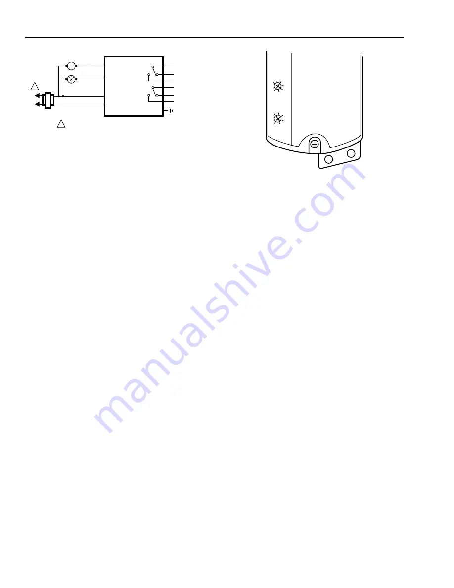
Fig. 6. ML7295 typical wiring diagram.
OPERATION
The ML7295 DCA is designed for use in HVAC installations to
operate dampers, ventilation flaps, louvers and valves requiring
up to 142 lb-in. (16 N•m) of torque. If the power fails, the
actuator spring returns it to the fail-safe position. The actuator is
designed for reversible mounting. The housing is asymmetrical
to indicate the spring return direction (see Fig. 2). As shipped
from the factory, the actuator drives from -5
°
to 90
°
(indicated
on the label) and spring returns back to -5
°
.
The ML7295 DCA is operated by a proportional controller.
When using a proportional controller, the actuator will be
driven toward its fully open position when the input signal
increases and toward its fully closed position when the input
signal decreases. The motor stops when the input signal
matches the desired proportional control point.
The actuator has a position indicator to show shaft position.
As the indicator moves with the shaft, it is an angular
representation of the shaft position; and it can be placed in
numerous distinct positions. Remove the indicator by simply
pulling it from the coupling. It can then be rotated and
repositioned at 5
°
increments using the two sets of three pins
on the coupling.
Adjustable Zero and Span (ML7295H only)
The ML7295H has the additional capability of adjustable zero
and span. Figure 7 shows the potentiometers U
0
and
∆
U.
These potentiometers are present only on the ML7295H
family of DCAs. A basic description of these potentiometers
follows:
U
0
(Zero adjust) is factory calibrated and provides a finer
adjustment for the input signal that will drive the motor
closed. It is factory set to 0 Vdc, and can be adjusted as
high as 5 Vdc.
∆
U (Span) is factory calibrated and adjusts the motor
response to travel full stroke through the selected input
span. It is factory set to 10 Vdc, and is adjustable from
2 to 30 Vdc.
L1
(HOT)
L2
1
1
24 VAC
METER
8 GREY
9 PINK
1 RED
S1 GREEN/RED
S2 GREEN/BLUE
S3 GREEN/PINK
S4 BLACK/RED
S5 BLACK/BLUE
S6 BLACK/PINK
GND GREEN
IN
OUT
T2
T1
2 BLACK
ML7295 ACTUATOR
M12452
POWER SUPPLY. PROVIDE DISCONNECT MEANS
AND OVERLOADPROTECTION AS REQUIRED.
SERIES 70 CONTROL
(MODULATING)
AUX
SWITCH
A
AUX
SWITCH
B
–
+
Fig. 7. ML7295H adjustable zero and span
potentiometers (factory setting).
Manual Override
The actuator can be operated with no power present. Use
this feature during installation or to move and lock the
damper or valve shaft position when there is no power.
To operate the manual override:
1. If the power is on, turn it off.
2. Insert the supplied key (Allen wrench) as shown in
Fig. 8.
3. Rotate the key in the direction indicated on the cover.
4. Once the desired position is reached, hold the key to
prevent the spring return from moving the actuator.
5. With the key held in place, use a screwdriver to turn
the gear train lock pin in the indicated direction.
NOTE:
No more than 1/8 turn of the lock pin is
required to engage the lock; a slight click is
heard and the pin resists further rotation.
6. Remove the key without rotating it further.
To release the manual override with no power present:
1. Insert the supplied key.
2. Turn the key 1/4 turn in the direction indicated on the
cover.
3. Remove the key without engaging the gear train lock pin.
4. The spring will return the actuator to the fail-safe
position.
Once power is restored, the actuator will return to normal
automated control.
M12453
FACTORY SETTING
2
5
CONTROL
SIGNALS
SPAN,
∆
U
OFFSET, Uo
10
15
20
25
30
0
1
2
3
4
5


