R7426D UNIVERSAL INPUT CONTROLLER
7
EN1B-0204GE51 R0403
The following rule-of-thumb formula are used for P+I+D
control:
•
Discharge air control
6
...
5
X
X
h
p
=
•
Room
control
12
...
10
X
X
h
p
=
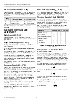
Resetting Time tr1 / tr2 (P.12 / P13)
In the case of combined action including proportional and
integral components (P+I control) the reset time (tr) is defined
as the required time after which the integral part is equal to
the change due to the proportional action for a predetermined
step change in the input variable. See Fig. 3.
The control parameter
tr1
sets the reset time of the P+I main
control loop. For limit or submaster cascade control (input
variable X2) the control parameter
tr2
sets the reset time of
these control loops (see Table 6).
If only proportional control is required parameter tr has to be
set to Off.
P
P
tr %/s
t
t
Y
X
w
tr
0
P = 100
X
p
X
w %
P
P
tr %/s
t
Y
tr
P = 100
X
p
X
w %
td
P v
d %
P + I controller
P + I + D controller
Fig. 3. Step change response of P+I and P+I+D control
Note:
P+I+D control is available for main control and main
control with limitation control.
In cascade control the submaster is P+I+D
controlled while the master is P+I controlled.
Setting Guidelines for Reset Time of
P, P+I and P+I+D Control
The reset time
tr
should be adjusted to 2...3 times of the
response time T
u
, which is the time interval between the
beginning of a sustained disturbance (e.g. rapid step change
of valve position) and the instant when the resulting change
in the output signal reaches a specified fraction of its final
steady-state value, either before overshoot or in the absence
of overshoot.
The response time T
u
in discharge air control is normally in
the range of 0.1 to 0.6min, which allows adjustments of the
reset time tr in a range of 0.2 to 2min.
In room control the response time T
u
is in the range of
0.5 to 5min, which results in a setting of 1 to 15min.
Derivative Decay Time td and Amplification
vd (P.27 / P.28)
The Propor In Derivative (P+I+D) control adds
the derivative function to P+I control to enhance the control
behavior. The derivative function opposes any change and is
proportional to the rate of change (derivative).
If the controlled input X1 deviates from the master setpoint
(CTRP1), the derivative function outputs a corrective action
to bring the control variable X1 back more quickly than by
integral action alone.
The derivative amplification
vd
determines the effect of
derivative action after a rate of change of the controlled input
X1.
The decay time
td
determines the decay of the control output
Y1 after derivative action (see Fig. 3).
Note:
In main control and cascade control applications the
control parameters
td
and
vd
determines the
derivative function. In main control with limitation
control these parameters determines the two
derivative functions of main control and limitation
control.
Setting Guidelines for Derivative Amplification and
Decay Time of P+I+D Control
The proper setting depends on the time constants, e.g. the
response time T
u
, of the system being controlled.
The parameter
vd
and
td
can be set in the following relation:
vd
T
0.42
td
u
⋅
=
In other words, with derivative amplification
vd
set to 1, the
decay time
td
should be set to approx. 0.42
⋅
T
u
or approx.
(0.15...0.25)
⋅
tr.
The response time T
u
in discharge air control is normally in
the range of 0.1 to 0.6min, which allows adjustments of the
decay time
td
in a range of 2.5 to 15sec.


