background image

MeshGuard User’s Guide 


31 

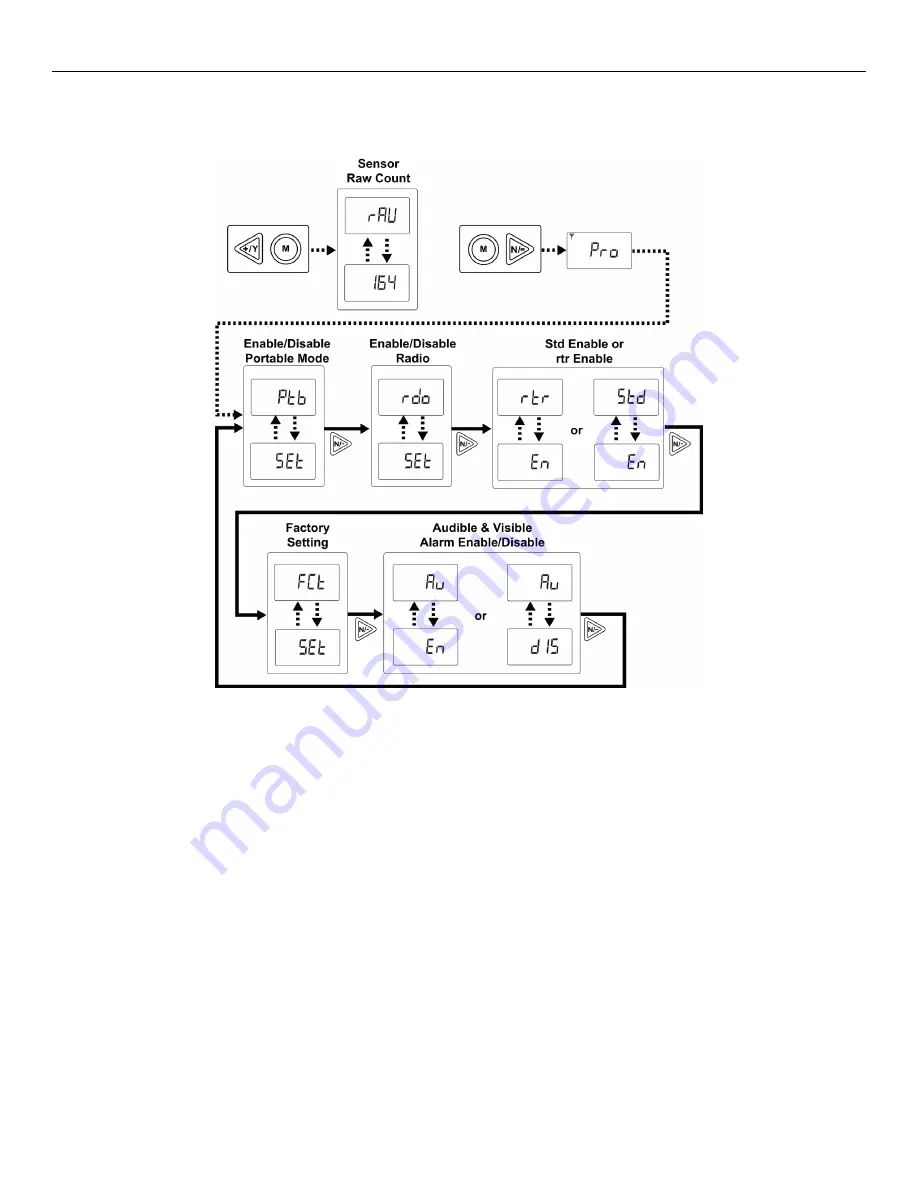
Enter this programming mode by first entering Diagnostic Mode.  Refer to “Entering Diagnostic Mode,” page 30. 


Step through the menus by pressing [N/-]. Exit by pressing [MODE], and then shutting off the MeshGuard and 

restarting it. 


Содержание MeshGuard FTD-2000

Страница 1: ...Rev K January 2019 P N D01 4002 000 MeshGuard TM Monitor User s Guide ...

Страница 2: ...2 Copyright 2019 RAE Systems by Honeywell ...

Страница 3: ... Change SPAN value 26 5 4 10 Change Pan ID 27 5 4 11 Join Mesh Network 27 5 4 12 Change Communication Interval 27 6 Diagnostic Mode 28 6 1 Entering Diagnostic Mode 28 6 2 Exiting Diagnostic Mode 28 6 3 Diagnostic Mode Readings 29 6 3 1 Sensor Raw Count 29 6 3 2 Battery Raw Count 29 6 3 3 Temperature Raw Count 29 6 3 4 Zero Raw Count 29 6 3 5 Calibration Delta Counts 30 6 4 Diagnostic Mode Programm...

Страница 4: ...be calibrated every time it does not pass a bump test but no less frequently than every six months depending on use and exposure to gas and contamination and its operational mode Calibration intervals and bump test procedures may vary due to national legislation Honeywell recommends using calibration gas cylinders containing the gas that is appropriate to the sensor you are using and in the correc...

Страница 5: ... Lithium battery or external rechargeable battery provided by RAE Systems This instrument has not been tested in an explosive gas air atmosphere having an oxygen concentration greater than 21 Substitution of components may impair suitability for intrinsic safety Replace batteries only in non hazardous locations STATIC HAZARD Clean only with a damp cloth For safety reasons this equipment must be op...

Страница 6: ...The detector has the option of relaying the wireless signal to other MeshGuards as needed to bypass obstacles The MeshGuard s built in radio board operates on a frequency of 2 4GHz and complies with IEEE 802 15 4 standard The FTD 2000 works with the FMC 2000 wireless controller on a flexible robust wireless network to provide reliable low cost operation It also works in a ProRAE net network with a...

Страница 7: ...llation no hardwiring involved Large area coverage with multi hop mesh network Field replaceable battery Loud audio alarm 90dB 30cm 12 Large easy to read continuous display Bright red flashing alarm Highly resistant to RFI interference IP 65 rated for outdoor use in harsh environments Sensors supported See section 14 MeshGuard Sensor Specifications Field replaceable sensor User adjustable high and...

Страница 8: ... virtually identical whether in a metal enclosure or a plastic enclosure Functionality is identical regardless of the enclosure 1 LED alarm 2 LCD with backlighting 3 Buzzer alarm 4 Sensor gas inlet 5 Battery cover on bottom 6 Y MODE and N keys 7 Antenna 7 1 2 3 6 5 Plastic Housing Metal Housing 4 ...

Страница 9: ...icator 3 Wireless Communication if on the monitor is in STD if blinking the monitor is RTR 4 Short Term Exposure Limit STEL 5 Time Weighted Average TWA 6 8 High Alarm 7 8 Low Alarm 9 Gas Concentration unit ppm 10 Gas Concentration unit 11 Save Setting 12 13 Span Calibration 14 Reading Value Remark Concentration unit is shown as either ppm 9 or 10 ...

Страница 10: ...Power Supply D size EVE or Xeno Lithium primary battery 3 6V 19 Ah Max Current Consumption 200mA 3 6V during transmission 0 5mA 3 6V during standby Operation Time Internal Battery For STD Mode up to 6 Months For RTR Mode up to 10 days STD is standard function device RTR is router function device Operating Temperature 40 to 122 F 40 to 50 C for CO and H2S sensors Other sensors 4 to 122 F 20 to 50 C...

Страница 11: ...d beeps The monitor is now on as indicated by the display The MeshGuard performs a self test followed by warm up and zero calibration The display briefly shows the firmware version for example F1 0 means firmware version 1 0 F2 0 means firmware version 2 0 etc Then the MeshGuard initializes the wireless network and displays this information Note If MeshGuard is unable to find a radio network to co...

Страница 12: ...nce The monitor is off when the display is blank Release the MODE key The MeshGuard is now off 4 3 Low Battery Indicator Action The MeshGuard s battery is designed for up to six months life in STD mode in RTR mode including the MeshGuard Router s normal operation battery life is up to 10 days When the battery gets low the MeshGuard beeps once per minute and an empty battery icon appears It is reco...

Страница 13: ...ate as a standard STD or a router mode RTR device In STD mode the MeshGuard transmits data to the host at a set interval the default is 30 seconds or anytime an alarm occurs In RTR mode the MeshGuard receives data in real time and it can also work as a router as needed to relay data from STD devices back to the host Note Operating the MeshGuard in RTR mode reduces battery life The interval can be ...

Страница 14: ...is the default The MeshGuard displays the current reading Pressing MODE steps through the Detection Mode screens Press MODE and it displays the sensor type Press MODE and it alternates between EUI Extended Unique Identifier and its value Press MODE and it alternates between Pan and ID Personal Area Network Identifier and its value Press MODE to return to the detector reading ...

Страница 15: ...a and returns to the detector reading 5 3Detection Mode When Portable Mode Is Enabled When Portable Mode is enabled see page 32 pressing MODE steps through three more screens STEL TWA and Peak The initial screen is the reading display Press MODE and it displays STEL The STEL short term exposure limit is the average reading of the gas concentration for the last 15 minutes Note The STEL reading does...

Страница 16: ...eighted average is the accumulated reading of the gas concentration divided by 8 hours since the monitor was turned on Press MODE and the display indicates the Peak reading by alternating between P for Peak and a numerical value Press MODE to return to the current reading ...

Страница 17: ... appearance Calibrate the MeshGuard Changing Preset Limits or Span Gas Values Set Pan ID Join network Choose communication interval The menus accessed in Programming Mode are Zero Calibration Span Calibration High Alarm Low Alarm STEL Portable Mode only TWA Portable Mode only Set Span Value Pan ID Join Network Communication interval ...

Страница 18: ...Pressing N steps you through all the screens and then returns to the first programming display Each display alternates between its name and a status message or value Note You can exit Programming Mode at any time by pressing MODE Also if you do not make a change within one minute the MeshGuard exits Programming Mode and returns to Detection Mode ...

Страница 19: ... Mode You may exit Programming Mode anytime and return to Detection Mode in either of these two ways Press MODE MeshGuard exits Program Mode and shows the current reading in Detection Mode Do not press any buttons for 1 minute MeshGuard automatically exits Programming Mode and returns to Detection Mode showing the current reading 5 4 3 Zero Calibration When CAL and go are displayed in alternation ...

Страница 20: ...y The LCD displays no and advances to the next programming menu Span calibration 5 4 4 Span Calibration CAL and go flash in alternation and SPAn is shown The MeshGuard is now ready to perform a span calibration To start calibration press Y The LCD displays go The MeshGuard waits for 10 seconds so that you have time to connect the calibration gas Connect the calibration gas adapter to the MeshGuard...

Страница 21: ... calibration should be repeated If the MeshGuard does not detect gas after counting down to 0 the LCD displays Err for error The LED glows red and the buzzer sounds to provide extra warning The MeshGuard automatically returns to the span calibration display In this case you should attempt another calibration If the span calibration fails a second calibration the sensor may need to be replaced Note...

Страница 22: ...etting Press MODE to go back to Detection Mode or N to advance to the next menu The LCD displays the current value Change the value if necessary To change the value 1 Press Y to increase the number and N to decrease it 2 Press MODE to advance to the next digit 3 After moving to the last digit and making changes press MODE A question mark is shown in the display asking if you want to save the chang...

Страница 23: ...to exit and return to Detection Mode or N to advance to the next menu The LCD displays current value Change the value if necessary To change the value 1 Press Y to increase the number and N to decrease it 2 Press MODE to advance to the next digit 3 After moving to the last digit and making changes press MODE A question mark is shown in the display asking if you want to save the change Press Y for ...

Страница 24: ... sensor type Press Y to enter and change the setting MODE to exit and return to Detection Mode or N to advance to the next menu The LCD displays current value Change the value if necessary To change the value 1 Press Y to increase the number and N to decrease it 2 Press MODE to advance to the next digit 3 After moving to the last digit and making changes press MODE A question mark is shown in the ...

Страница 25: ...erent sensor types Press Y to enter and change the setting MODE to exit and return to Detection Mode or N to advance to the next menu The LCD displays the current value Change the value if necessary To change the value 1 Press Y to increase the number and N to decrease it 2 Press MODE to advance to the next digit 3 After moving to the last digit and making changes press MODE A question mark is sho...

Страница 26: ...e next menu The LCD displays the current value Change the value if necessary To change the value 1 Press Y to increase the number and N to decrease it 2 Press MODE to advance to the next digit 3 After moving to the last digit and making changes press MODE A question mark is shown in the display asking if you want to save the change Press Y for yes The message dn means the change is done Press N fo...

Страница 27: ...eans that the change was abandoned Press MODE to return to the first digit 5 4 11 Join Mesh Network Press Y to initiate joining a network Three bars flash in sequence while it searches When it is done it alarms once and displays dn for done 5 4 12 Change Communication Interval This menu allows you to change the interval between wireless transmissions SET and ItUL flash to indicate that you can cha...

Страница 28: ...the display shows rAU followed by a number The following chart shows how to navigate Diagnostic Mode pressing N repeatedly steps through the screens 6 2 Exiting Diagnostic Mode Note You can exit Diagnostic Mode and enter Programming Mode and calibrate the MeshGuard as usual by pressing both MODE and N for three seconds Note You can exit Diagnostic Mode and enter Detection Mode by pressing MODE and...

Страница 29: ...ss N to advance to the next reading 6 3 2 Battery Raw Count Battery Raw Count is indicated by bAt followed by a number Press N to advance to the next reading 6 3 3 Temperature Raw Count Temperature Raw Count is indicated by tNp followed by a number Press N to advance to the next reading 6 3 4 Zero Raw Count Zero Raw Count is indicated by 0rC followed by a number Press N to advance to the next read...

Страница 30: ...advanced programming functions These include Enable Portable Mode Enable Radio Enable STD or RTR Return MeshGuard to original factory settings Enable disable audible and visible alarms Note When the MeshGuard is in this programming mode if you do not make a change or press a key for 60 seconds it reverts to the standard Diagnostic Mode Important After you make changes in Diagnostic Mode it is reco...

Страница 31: ...de 31 Enter this programming mode by first entering Diagnostic Mode Refer to Entering Diagnostic Mode page 30 Step through the menus by pressing N Exit by pressing MODE and then shutting off the MeshGuard and restarting it ...

Страница 32: ... this screen Note dIS means fixed Portable Mode disabled and En means portable Portable Mode enabled 6 4 2 Radio Enable Disable The next menu is for setting turning the MeshGuard s radio on or off SEt and rdo flash in alternation to indicate that the MeshGuard radio can be turned on enabled or off disabled The default value is on Press Y to enter and change the setting MODE to exit and return to D...

Страница 33: ...o its original factory settings Note This function clears all custom settings and returns all settings their factory default values This cannot be undone 6 4 5 Audible Visible Alarm Enable Disable Press Y to toggle between the MeshGuard s audible and visible alarms turned on and off ...

Страница 34: ...rds inside of the unit 4 Replace the battery cover by turning it clockwise with the 3 pin end of the tool Note Only change internal battery in a safe location and use the battery RAE Systems provided P N 500 0111 000 model ER34615 or XL 205F After changing the battery wait at least 60 seconds before turning the MeshGuard on Battery Battery cover 3 pin end Hexagonal end Sensor compartment Battery c...

Страница 35: ... 3 pin end of the tool to unscrew and open the filter holder by turning it counterclockwise 2 Remove and discard the filter 3 Place a new filter inside the monitor 4 Replace the filter holder by turning it clockwise with the 3 pin end of the tool Filter Filter holder ...

Страница 36: ...to the compartment Important Ensure that the RAE Systems part number matches the sensor that was removed WARNING Use only the same sensor model as the one installed when the monitor was purchased 5 Replace the sensor compartment cover using by turning it clockwise using the hexagonal end of the tool 6 Replace the filter holder by turning it clockwise using the 3 pin end of the tool Note Always rec...

Страница 37: ...controller Controller does not receive completed data packet Battery is low MeshGuard and controller have different Pan ID numbers The distance should be 300 m line of sight Deploy RTR MeshGuard or MeshGuard Router s Relocate the MeshGuard or deploy RTR MeshGuard or MeshGuard Router s Press Y on the detector to force it to send data packets Replace battery Set both units to have the same Pan ID nu...

Страница 38: ...ximumvalue ofthesensor 3 beeps per second High Alarm high alarm setting 3 beeps per second Low Alarm low alarm setting 2 beeps per second TWA TWA setting 1 beep per second STEL STEL Setting 1beep per second Zero Drift 0 ppm 1 beep per second Battery Low 3 2V 1 beep per minute Battery Exhausted 3 1V 1 beep per second ...

Страница 39: ...d uses a specially designed stainless steel enclosure that is permanently mounted It protects the plastic body MeshGuard from damage in industrial settings 10 1 Magnet Mount Installation This magnet is powerful enough to support the MeshGuard when it is placed against a flat steel or iron surface Important Keep the magnet away from computer hard drives The strong magnet can corrupt or erase data o...

Страница 40: ... Four reinforced holes in the rear of the enclosure allow for a screw to pass through to the mounting brackets The enclosure can be mounted to a vertical or horizontal pole Side View Front View Mounting Holes Sensor Cover Vertical pole Horizontal pole ...

Страница 41: ...al pole Loosely assemble the clamp parts around the pole Note that the screws have nuts that fit into the clamp parts The clamp parts are designed to hole the nut so that you do not need to use a wrench Hand tighten the parts until snug Tighten the hex screws from the front of the enclosure Once the clamp parts and the enclosure are securely held against the pole stop tightening Note The pole must...

Страница 42: ...cover of the enclosure 4 Insert the hex screw into the cover s locking portion and tighten it 5 The MeshGuard is now ready to use Note The sensor cover on the bottom of the enclosure can be removed so that the filter and sensor can be inspected without removing the MeshGuard from the enclosure Simply pull off the cover and follow the maintenance procedures in this guide 1 2 5 4 3 ...

Страница 43: ...nclosure instead of the clamps This approach provides the protection of the enclosure with the ease of installation afforded by the magnetic mounting 1 Insert screw through magnetic disc 2 Place the magnetic disc over the bottom hole on the rear of the enclosure 3 Tighten the screw until the disc is snug Side View Rear View ...

Страница 44: ...10 30 sec 20 C to 50 C 4 F to 122 F SO2 0 to 20 ppm 0 to 100 ppm 0 1 ppm 1 ppm T90 60 sec T10 60 sec 20 C to 50 C 4 F to 122 F HCN 0 to 50 ppm 0 5 ppm T90 200 sec T10 200 sec 20 C to 50 C 4 F to 122 F NO 0 to 250 ppm 0 5 ppm T90 45 sec T10 45 sec 20 C to 50 C 4 F to 122 F PH3 0 to 20 ppm 0 1 ppm T90 60 sec T10 60 sec 20 C to 50 C 4 F to 122 F HCL 0 to 15 ppm 1 ppm T90 200 sec T10 200 sec 20 C to 5...

Страница 45: ...fer to the serial number of the instrument The letter in the serial number indicates the year of manufacture For example M indicates the manufacturing year is 2010 Letter Year V 2018 W 2019 A 2020 B 2021 C 2022 D 2023 E 2024 F 2025 G 2026 H 2027 I 2028 J 2029 K 2030 ...

Страница 46: ...For more information www raesystems com D01 4002 000 Rev K January 2019 2019 Honeywell International ...

Отзывы: