Limitless™ WPMM Series
Issue 2
50051864
Honeywell Sensing and Control 15
6
FUNCTIONAL INDICATORS AND MODES/DIAGNOSTICS
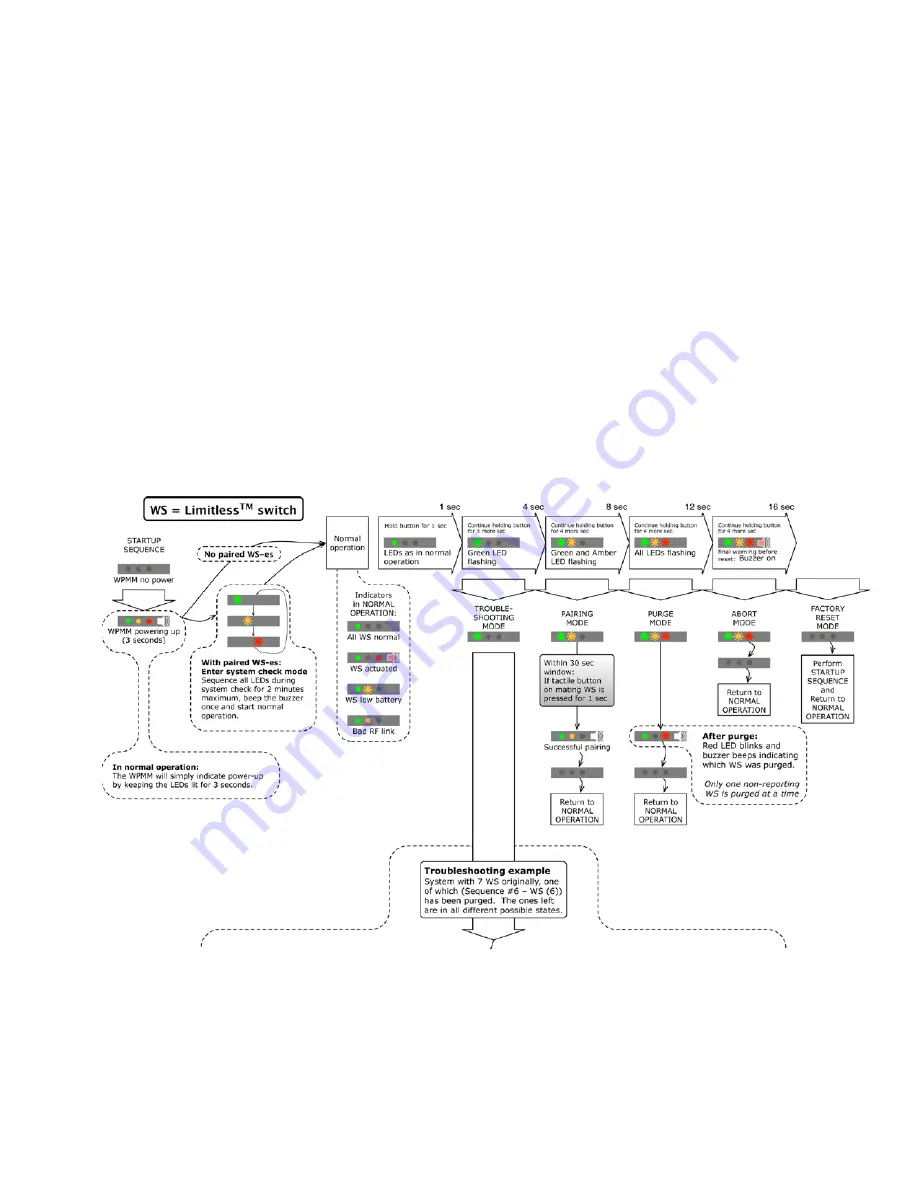
The operation and LED functions for the WPMM are visually depicted and described below. These graphics are also
located as a separate file on this CD or at6.1
Principle of Operation of the WPMM and Limitless™ Switch
A Limitless™ switch will send an RF signal to the WPMM when the actuator of the switch changes position. There
are up to 16 Limitless™ switches that will communicate and thus indicate their actuation position with a single
WPMM. The actuation (Free Position to Full Overtravel) of any one of the Limitless™ switches will cause a single
red output LED to illuminate, a buzzer to sound and a change in the NPN output. However, there will be no
differentiation of outputs (visual, audible or NPN state change) between the Limitless™ switches (up to 16) being
actuated. Further, if a Limitless™ switch is actuated and thus causes the single red output LED to illuminate, a
buzzer to sound and a change in the NPN output, actuation of another Limitless™ switch(s) will not cause another
output change (visual, audible or NPN state change). A further detailed description of each function is defined in the
following sections.
Figure 7. WPMM Operation and LED Functions Chart – part 1


