


GB-5
D
GB
F
NL
I
E
Assistance in the event of
malfunction
DANGER
Electric shocks can be fatal! Before working on
possible live components, ensure the unit is discon-
nected from the power supply.
Fault-clearance must only be undertaken by author-
ized trained personnel.
▷
Faults may be cleared only using the measures
described below.
▷
If the control unit (BCU) does not respond even
though all faults have been remedied: remove
the unit and return it to the manufacturer for
inspection.
▷
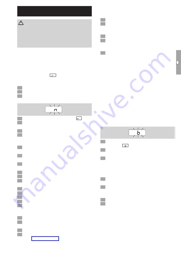
If a fault message (
0
) is active, the control unit
can continue to be operated via its digital inputs.
?
Faults
!
Cause
•
Remedy
0
? The display blinks and indicates
0
.
!
No connection established between BCU and
PLC (controller).
•
Check the wiring.
•
Check the PLC program to ensure that the net-
work name and IP configuration of the BCU are
valid.
•
Switch on the PLC.
Or
? A bus fault is indicated on the automation
system.
!
The PROFIBUS DP data traffic has suffered a
fault.
!
Bus cable interrupted.
•
Check cable.
!
Incoming and outgoing bus cables confused in
the plug.
•
Check the wiring.
!
A and B cables confused.
•
Check the wiring.
!
Terminal resistors connected incorrectly.
•
Switch on the terminal resistors on the first and
last subscriber in the segment and switch them
off for all other subscribers.
!
Incorrect PROFIBUS address set.
•
Correct the address setting – switch the unit off
and then on again to save the address.
!
Bus cables too long.
•
Reduce cable length or baud rate – see
▷
If the transfer rate is reduced, remember that
this will increase the signal running times to and
from the individual units.
!
Poor shielding.
•
Check whether the shield is connected to the
shield clips in the PROFIBUS DP plugs in full and
over a wide area.
!
Poor equipotential bond.
•
Check whether the PROFIBUS DP shield is con-
nected at all points to the same ground potential
via the grounding system of the units.
•
If necessary, an equipotential bonding cable must
be laid.
▷
If faults occur sporadically in the PROFIBUS DP
system, and are only indicated briefly in the bus
master, the following points in particular should
be checked:
– Terminal resistors,
– Shield,
– Cable lengths/routes,
– Equipotential bond,
– Use of interference-suppressed spark electrode
terminal boots (1 kΩ).
▷
For information on planning and the structure of
a PROFIBUS network and the components to
be used (e.g. cables, lines and switches), see
www.profibus.com or the instructions for the
automation system.
E
E
?
The display on the control unit blinks and
indicates
E E
.
!
Internal communication with bus module has
suffered a fault.
•
Connected control elements must be equipped
with protective circuits in accordance with the
manufacturer’s instructions.
▷
This prevents high voltage peaks which can
cause malfunctioning of the BCU.
•
Use interference-suppressed terminal boots
(1 kΩ).
•
If the fault cannot be remedied by doing this,
remove the unit and return it to the manufacturer
for inspection.
!
Bus module is defective.
•
Replace the bus module.
For other control unit fault messages, see
BCU 46x, 480 operating instructions, section
entitled “Assistance in the event of malfunction”.