SYSTEM DESCRIPTION AND INSTALLATION MANUAL
HS--700 High Speed Data System
23--20--33
30 Aug 2002
Use or disclosure of information on this page is subject to the restrictions in the proprietary notice of this document.
Page 3--1
SECTION 3
ELECTRICAL INSTALLATION
1. Overview
A. General
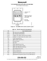
(1) This section gives electrical installation procedures, power distribution, and
interconnect information for the HSU, combiner, and splitter.
(2) Procedures for proper shield, power, and signal grounding are also provided in this
section. In addition, procedures for the various buses are included.
B. Equipment and Materials
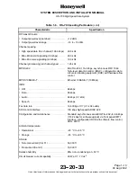
(1) See leading particulars table for a list of mating connectors required to do the
electrical installation.
2. Electrical Installation Procedure
A. General
(1) The information necessary to provide the electrical interconnects is contained in the
following paragraphs.
B. Power Requirements
(1) The aircraft dc power supply must be 28 V dc (nominal). The normal minimum and
maximum voltages permitted are 20.5 and 32.2 V dc respectively.
(2) Power supply to the HSU -- The voltage level of the power supplied to the HSU is
important in this installation. The potential is the difference between the power pins
and power ground pins at the line replaceable unit (LRU). Excessive voltage drops in
the power wire(s) and power ground wire(s) cause one or more of the following
conditions:
•
The LRU draws additional current from the aircraft supply system.
•
The voltage drop can become large enough that the LRU oscillates on and off at
low line. This oscillation can damage the LRU.
(3) The HSU is supplied from the 28 V dc aircraft power system through a separate
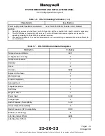
circuit breaker. It is essential to keep the impedance of the power supply cables
below the limits specified in Table 1-6. The HSU also provides the power supply
voltages to the CDM.
(4) The recommended maximum total combined voltage drop (voltage drop of the power
wire[s] plus voltage drop of the power ground wire[s]) low line input is 1.0 V. Voltage
drop is a function of current and resistance (resistance in this case is a function of
wire gauge and wire length). See Figure 3-1 for determining proper wire gauge for a
round trip length of LRU power and power ground wires.


