MERLIN NX IP AND MST/TP VAV CONTROLLER - INSTALLATION INSTRUCTIONS
EN1Z-1076GE51 R0722
26
— Ground noise should not exceed the EIA-485 com
-
mon mode voltage limit.
— Must conform to TIA/EIA 485 cabling guidelines.
“TIA/EIA 485 Cable Specifications” on page 19.
— Should not extend beyond a single building.
— It is recommended that you select a low baud rate
(for example, 19.2 kbps) for reliable operation
.
SYLK BUS™
Sylk™ Bus capable wall modules such as CLCMTR40x /
CLCMTR42x can be connected to the controller's Sylk™
Interface (terminals 14 and 15).
• The Sylk™ Bus is single pair, and polarity-insensitive.
• Maximum current provided at the Sylk™ Bus interface:
96 mA.
• The maximum number of wall modules depends on the
following wall module specific information:
— Sylk™ bus power consumption
— Number of parameters used
— Total config file size
The Niagara tool has an inbuilt resource calculator to
calculate the number of Sylk™ wall modules.The Sylk™
devices supported by the MERLIN NX IP and MSTP VAV
are;
Supported wall modules
CLCMTR40, CLCMTR40-H, CLCMTR40-H-CO2,
CLCMTR40-CO2, CLCMTR42, CLCMTR42-H,
CLCMTR42-H-CO2, CLCMTR42-CO2, CLCMTR71-H,
CLCMTR120 (TR75E) and CLCMTR120-H (TR75-HE)
NOTE:
The CLCMTR42x Wall Module must be version
1.00.3 or higher.
NOTE:
CLCMTR70 Wall Modules are not supported.
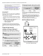
Sylk Bus Wiring Examples
Fig. 33. Sylk™ Wiring Topologies
Table 9. Recommended max. distances from controller
to CLCMTR40x/CLCMT42x wall modules
Single twisted pair, Non-Shielded,
Stranded or Solid
c)
Standard non-twisted
thermostat wire
shielded or Non-
Shielded, Stranded or
Solid
d)
18 - 22 AWG
(0.33 to 1mm2)
24 AWG
(0.20 mm2)
18 - 24 AWG
(0.20 to 1 mm2)
500 ft
(150 m)
400 ft
(120 m)
100 ft
(30 m)
c)
As a rule of thumb, single twisted pair (two wires per cable,
only), thicker gauge, non-shielded cable yields the best results
for longer runs.
d)
The 100 ft (30 m) distance for standard thermostat wire is
conservative but is meant to reduce the impact of any sources
of electrical noise (incl. but not limited to VFDs, electronic
ballasts, etc.). Shielded cable recommended only if there is a
need to reduce the effect of electrical noise.
These distances apply also for shielded twisted pair.
Table 9. Recommended max. distances from controller
to CLCMTR40x/CLCMT42x wall modules (Continued)
Single twisted pair, Non-Shielded,
Stranded or Solid
c)
Standard non-twisted
thermostat wire
shielded or Non-
Shielded, Stranded or
Solid
d)
Number of Devices: Subject to power loading - refer to device
documentation).
to additional
Sylk devices
OVERRIDE
FAN
polarity
independent
IP VAV
IP VAV
Sylk Device
e.g. TR40, TR42.
14 15
Home Running
Daisy Chaining


