61-86-03-13
Page 7
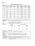
Specifications – Actuator
Electrical
Input Signals
Analog
: 0/4 to 20 mA (With supplied 250 ohm shunt resistor for current range)
0/1 to 5 Vdc
0 to 10 Vdc
Digital
: Remote Setpoint via Modbus RTU (RS485)
Input Impedance
Input
0/4 to 20 mA
0/1 to 5 Vdc
Input Impedance
250
ohms
10 K ohms
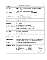
Input Characterization
Provides characterization of the input signal.
Selections are: Linear, Square Root or Custom.
Sensitivity
0.2 % to 5 % of 90° span, proportional to deadband
Hysteresis
Less than 0.4 % of full scale
Deadband
0.2 % to 5 % of 90° span, adjustable. Shipped at 0.5%
Repeatability
0.2 % of 90° span
Voltage/ Supply Stability
0.25 % of span with +10/
-
15 % voltage change
Temperature Coefficient
Less than
±
0.030 % of span per degree C for 0 °C to 50 °C
Less than
±
0.05 % of span per degree C for
-
30 °C to 65 °C
Zero Suppression
90% of span
Input Filters
Selectable spike and low pass filters
Solid State Motor Control
CW/CCW open collectors (opto-isolators) for use as discrete control inputs to the inverter
for motor operation.
Failsafe operation
If input signal exceeds configured input range. Selectable and adjustable.
Feedback signals/Output
0 to 20 mA, 4 to 20 mA
0 to 5 Vdc, 1 to 5 Vdc with 250 ohm resistor; (0 to 16 Vdc with 800 ohm resistor)
Slidewire Emulation
Provides output voltage ratiometric to shaft position and potentiometric to supply voltage
(1 to 20 Vdc) without a slidewire. Emulates a 100 ohm to 1000 ohm slidewire. 10 mA
output maximum.
Isolation
Input signal, output signal and power are isolated from each other.
Load Requirement (4-20)
Current Out — 0 to 1000 ohms
Programmable Functions
Selectable and configurable operating parameters:
•
Input range
•
Input filtering
•
Input characterization
•
Security
•
Digital Input action
•
Deadband
•
Failsafe on loss of
input signal
•
Failsafe on loss of
position sensor
•
Direction of rotation
•
Relay closure
action
•
Communication
parameters
•
Split range
operation
•
Output range
•
Alarms


