background image

24

6.2.2

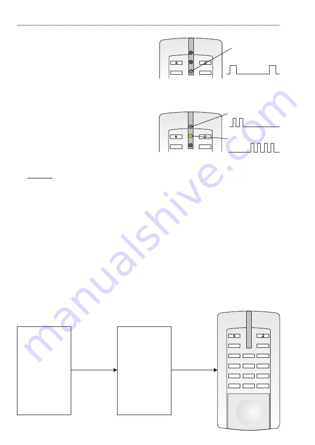
The address allocation mode at the

is

indicated by the bottom flashing green LED (lights
up briefly followed by a long pause

Switch off the address allocation mode in NetEdit.

reader

).

Activate address allocation mode

In

NetEdit,

the

address

allocation

mode

is

preselected and the reader informed via the ACS-8.

6.2.4

Manual address allocation via NetEdit

Enter the unique number (serial number) of a new reader plus the desired address when
programming NetEdit and transmit to the ACS-8. The ACS-8 transmits the unique number plus the
address to the reader. If the received unique number corresponds with the number defined in the
reader, the reader stores the address.
Address acknowledgement: After approx. 1 sec., the LEDs indicate the newly allocated address
(see 6.2.3).

F

I

Tens digit (green)

Units digit (yellow)

This example shows address 24

ACS-8

Programming

NetEdit

Enter unique

number

plus address

Unique number

address

+

F

i

2

3

6

5

4

7

8

9

3

0

r

1

Unique number

address

+

6.2.3

Address indication

The address allocation mode must be activated.

The address indicator is for monitoring newly defined
addresses or for a later control.

(green)

Each flash indicates the tens digit of the allocated
address.

Flashes 2 x = 20

Each flash indicates the ones digit of the allocated address.
Example:

Flashes 4 x = 4

The address allocation mode is then displayed in the lower LED.

Hold the transponder briefly in the reading range of the reader. A brief acoustical acknowledgement
confirms the request to display and restarts the display sequence. The bottom LED remains dark when
the address is displayed.

- Tens digit:

Upper LED

- Units digit:

Middle LED (yellow)

Repeat display of addresses:

Example:

Mounting and Operating Instructions - proX2-reader "Accentic" with keypad

F

I

Address allocation
mode indicator

Содержание 026421.10

Страница 1: ...centic mit Tastatur Art Nr 026421 10 Art Nr 026421 20 RS 485 und Clock Data Schnittstelle Wiegand Schnittstelle Montage und Bedienungsanleitung P31116 45 002 05 2017 06 28 Änderungen vorbehalten ZBLW2 00 0V03 xx D GB ...

Страница 2: ...2 Sicherheitshinweise Lesen Sie die Anleitung sorgfältig und vollständig durch bevor Sie das Gerät installieren und in Betrieb nehmen Sie erhalten wichtige Hinweise zur Montage Programmierung und Bedienung Das Gerät ist nach dem neuesten Stand der Technik gebaut Benutzen Sie das Gerät nur bestimmungsgemäß und in technisch einwandfreiem und ordnungsgemäß eingebautem Zustand gemäß den technischen Da...

Страница 3: ...neutrale Beschriftung der LEDs und der Tastatur Abriebfeste 10er Komforttastatur mit 6 zusätzlichen Funktionstasten Taktile und akustische Rückmeldung Nachtdesign mit zeitbegrenzter Hintergrundbeleuchtung Ein neues Auswerteverfahren garantiert äußerst stabile Übertragungen Automatische Erkennung und Verarbeitung der verschiedenen Transpondertypen EM 4102 EM 4150 Halbautomatische Reichweitenanpassu...

Страница 4: ... einen Transponder zu lesen sendet der Leser ein elektromagnetisches Feld mit einer Fre quenz von 125 kHz aus Sobald sich ein Transponder in diesem Feld befindet sendet dieser einen verschlüsselten Code im Energiefeld zum Leser zurück Jeder Transponder ist ein Unikat Novar Transpondern mögliche ID Träger siehe 9 Zubehör 4 Montage 4 1 Abmessungen in mm F i 2 3 6 5 4 7 8 9 3 0 r 1 60 75 32 54 142 Ge...

Страница 5: ...inderkopfschraube mit Unterlegscheibe Auf der Standard uP Dose Halbrund Holzschraube mit Schlitz und Unterleg scheibe Zur weiteren Befestigung kann bei Bedarf die dritte Montagebohrung Verwendung finden siehe 4 1 Die Schraubenlänge ist ebenfalls dem Montageuntergrund anzupassen Für die Montage empfehlen wir das Anschlusskabel nach Möglichkeit von hinten durch ein Leerrohr mit genügend Kabelreserve...

Страница 6: ...te Schnittstelle Für eine sichere Funktion ist zu beachten dass das 6 m lange Anschlusskabel auf max verlängert werden darf Zur Verlängerung kann z B ein Kabel der Ausführung JY ST Y 6x2x0 6 mm Verwendung finden Der Leser kann bis zu 1200 m abgesetzt werden Als Anschlusskabel wird Cat 5 empfohlen Ist der Leser der letzte Teilnehmer auf dem RS 485 Modulbus muss vor dem Leser ein Verteiler mit einem...

Страница 7: ...nummer des Lesers plus die gewünschte Adresse wird über die Programmierung eingegeben Die Adresse wird anschließend im Leser abgespeichert siehe 6 2 5 Mit einem beliebigen Transponder im Lesefeld des Lesers wird der Vorgang gestartet Die Adresse wird automatisch vergeben und anschließend im Leser abgespeichert Solange der Adressvergabemodus aktiv ist können auf diese Weise mehrere Leser nacheinand...

Страница 8: ...ken 20 gelb Transponder kurz ins Lesefeld des Lesers halten Eine kurze akustische Quittierung bestätigt die Anzeigeaufforderung und startet erneut den Anzeigeablauf Die untere LED bleibt während der Adressenanzeige dunkel Die Adressenanzeige dient der Kontrolle neu ange legter Adressen und der späteren Kontrolle Jedes kurze Aufleuchten zeigt die Einerstelle der vergebenen Adresse an 4 x blinken 4 ...

Страница 9: ...e kann einem Leser vor Ort eine bestimmte Adresse zugewiesen werden Die Plausibilitätsprüfung im ZK System verhindert dass eine Adresse mehrfach belegt werden kann Bei jeder Tastenbetätigung erfolgt eine Quittierung Klick Eine begonnene Adresseingabe kann durch wieder verworfen werden Adresse 1 oder 2 stellig eingegeben und mit OK Taste bestätigen Die Adresse wird zum ACS 8 gesendet und dort überp...

Страница 10: ... und Transponder zu verändern Zu beachten ist dass je nach Montageuntergrund eine Mindest und Maximalreichweite nicht unter oder überschritten werden kann Besonders bei einem Montageuntergrund aus Metall empfehlen wir den Abgleich durchzuführen Ein beliebiger Transponder wird im gewünschten Abstand zum Leser gehalten Die Leseeinheit verändert nun stufenweise die Energie des elektromagnetischen Fel...

Страница 11: ...n NetEdit oder im stand alone Programmier modus siehe Kap 7 wieder ausgeschaltet Wichtige Hinweise zum Abgleich Abgleich durchführen obere grüne LED Quittierung Signalton Während des Abgleichs muss der Transponder sehr ruhig im Lesefeld gehalten werden weshalb wir einen nichtmetallischen Gegenstand als Abstandshalter empfehlen Beliebigen im gewünschten Abstand zum Leser halten Sobald der Transpond...

Страница 12: ...er Abgleichmodus wird beendet Im Auslieferungszustand ist die Hintergrundbeleuchtung für den Ruhezustand kein Bedienvorgang abgeschaltet Sie wird nur für 5 Sekunden mit voller Helligkeit aktiviert wenn eine Taste betätigt oder ein Transponder ins Lesefeld gehalten wird Bedienvorgang Wird eine permanente Hintergrundbeleuchtung gewünscht kann die Helligkeit für den Ruhezustand mit den Tasten 4 und 5...

Страница 13: ...ertragungsreichweite ist abhängig vom Montageuntergrund und den verwendeten Transpondern Die folgenden Angaben beziehen sich auf eine Reichweite bei Verwendung einer ID Karte Nichtmetallischer Montagegrund bis ca 80 mm bei ID Karte Stahl als Montagegrund bis ca 60 mm bei ID Karte Aluminium als Montagegrund bis ca 70 mm bei ID Karte Schnittstellen RS 485 und Clock Data Gehäuse Abmessungen B x H x T...

Страница 14: ...e etwa in dieses Feld gehalten werden mittig Beeinflussung des Lesevorgangs durch andere Datenträger Um eine mögliche Beeinflussung mehrerer Datenträger beim Lesevorgang zu verhindern ist darauf zu achten dass der gewünschte Daten träger möglichst separat ins Lesefeld gehalten wird richtig falsch IK Datenträger Schlüsselanhänger IK Datenträger Karte IK Datenträger Armbanduhr 10 2 Bedien und Anzeig...

Страница 15: ...d Ihrer Anlage entsprechend ankreuzen PIN Türcode eingeben 0 9 und oder Datenträger ins Lesefeld halten ID möglich 10 5 Steuerfunktionen Makros aufrufen möglich gelb grün rot Farbe Grund Nach Lesung Bedeutung zustand einer Karte oder Tastatur eingabe gelb an Betrieb lesebereit gelb aus Gerät ist spannungslos PIN Code oder Türcodeeingabe ist aktiv nur RS 485 Schnittstelle grün an Dauerfrei rot an D...

Страница 16: ...Honeywell Security and Fire Solutions www honeywell com security de Novar GmbH Johannes Mauthe Straße 14 D 72458 Albstadt P031116 45 002 05 2017 06 28 2017 Novar GmbH ...

Страница 17: ...tic with keypad Item no 026421 10 Item no 026421 20 RS 485 and Clock Data interface Wiegand interface Mounting and Operating Instructions ZBLW2 00 0V03 xx Subject to change without notice D GB P31116 45 002 05 2017 06 28 ...

Страница 18: ...using and keypad with soft lint free dry cloth or one that has been lightly dampened with water Abrasive cleaners or chemicals of any kind will damage or discolour the surface of the housing Mounting and Operating Instructions proX2 reader Accentic with keypad Table of Contents Page 1 19 2 Interfaces 20 3 Functional description 20 4 20 5 Connection diagram 22 6 Start up 23 8 2 9 29 10 Operating 30...

Страница 19: ...eplaceable in different colours Neutral labelling of LEDs and keypad Abrasion resistant 10 key keypad with 6 additional functional keys Tactile and acoustical acknowledgement Night design with time limited luminous background New evaluation process ensures extremely stable transmission Automatic identification of different transponder types EM 4102 EM 4150 Semi automatic range adaptation is possib...

Страница 20: ...In order to read a transponder an electromagnetic field with a frequency of 125 kHz is transmitted from the reader unit As soon as a transponder enters this field it transmits a code in the power field to the reader The individual code of every transponder renders it unique central control unit central control unit The state is indicated via 3 LEDs ready authorized not authorized A buzzer is integ...

Страница 21: ...t at the bottom and unhook at the top When installing the housing back remove the electronics to avoid damage The housing back has two 60 mm boreholes for wall and f m sockets To fix securely use screws that are suitable for the mounting surface in question In metal Fillister head screw M3 x 30 mm min with washer On the standard s m socket Semi circular wood screw with slot 3 0 x 40 mm and washer ...

Страница 22: ...nstallation it usually has to be cut off 5 2 Synchronization In order to prevent densely packed readers from affecting one another they must be connected to one another via the Synchronization line black Up to 4 readers can be synchronized in this manner Synchronization is required at a distance of approximate value The transponder that is identified first has priority during the read process The ...

Страница 23: ...serial number of the reader plus the desired address via the programming of the central control unit The address is then stored in the reader see 6 2 5 Start the process with a transponder in the reading area of the reader The address is allocated automatically and then stored in the reader As long as the address allocation mode is active several readers can be automatically allocated addresses in...

Страница 24: ...en Units digit yellow This example shows address 24 ACS 8 Programming NetEdit Enter unique number plus address Unique number address F i 2 3 6 5 4 7 8 9 3 0 r 1 Unique number address 6 2 3 Address indication The address allocation mode must be activated The address indicator is for monitoring newly defined addresses or for a later control green Each flash indicates the tens digit of the allocated ...

Страница 25: ...ddress allocation mode must be activated When using this allocation mode a specific address can be allocated to a reader on site The plausibility check in the AC system prevents an address from being allocated more than once Every activated key is acknowledged by a click An address entry can be rejected by an Enter the new address with 1 or 2 digits and acknowledge with OK key The address is trans...

Страница 26: ...short of or exceed a minimum maximum range depending on the mounting surface Basically the range should be adapted to a metal mounting surface It is assumed that the maximum possible transmission range is lower on a metallic surface than on a non metallic surface Hold a transponder at the required distance to the reader The reading unit in the reader alters the power of the electromagnetic field i...

Страница 27: ...t hold the transponder steadily in the reading range We recommend using a non metallic object as a spacer between the reader and the transponder Adjust reader As soon as the transponder is identified begins to flash Adjustment begins LED indicator see above After approx 5 sec adjustment is completed Acknowledgement Brief Important Hold a transponder at the desired distance to the adjustment indica...

Страница 28: ... the transponder not being fully identified the first time it is held in the reading range The antenna is permanently activated using button 8 re establishes the state at the time of delivery cyclical actuation Button 4 Button 5 Button 8 Button 7 7 Stand alone programming mode To program in this mode only the 12 V DC operating voltage is required 7 2 Clear address 7 3 Load standard values 7 4 Adju...

Страница 29: ...ead mode c status indication 026421 10 Wiegand 026421 20 Connecting cable 12 core shielded 6 m Frequency range transmission power 125 kHz 10 dBµA m Protection category as per EN 60529 IP 65 Environmental class as per VdS III Operating temperature range 25 C to 55 C 9 Accessories 023314 023315 023316 99 023501 023329 Front white aluminium similar to RAL 9006 PU 3 pce Front pure white similar to RAL...

Страница 30: ...rrier should be held approximately in the of this range middle Influence on the read process by other data carriers In order to prevent several data carriers affecting the read process ensure that the desired data carrier is held separately if possible in the reading range Correct Incorrect IK data carrier key fob IK data carrier card IK data carrier watch 10 2 Operating and indication elements F ...

Страница 31: ...ellow green red Color Basic After reading Meaning condition a card or after a keystroke yellow on Operation ready to read off Device is idle PIN Code or door code entry is active only possible with RS 485 interface green on Permanently released red on Permanently blocked green on Door release red on ID card not authorized red blinking Read error yellow possible possible 0 9 and or ID Enter PIN or ...

Страница 32: ...Honeywell Security and Fire Solutions www honeywell com security de Novar GmbH Johannes Mauthe Straße 14 D 72458 Albstadt P031116 45 002 05 2017 06 28 2017 Novar GmbH ...

Отзывы: