HRR216PKA
CAM PULLEY/CRANKSHAFT/PISTON/ CYLINDER BLOCK
9-5
OIL PAN REMOVAL
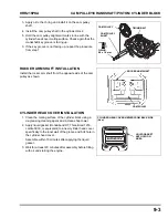
1. Set piston at TDC of compression stroke.
2. Remove the 6 x 25 mm flange bolts
3. Insert a screwdriver or equivalent tool into the recess as
shown, and remove the oil pan from the cylinder block.
Be careful not to damage the sealing surfaces. Use a tool
that fits tightly into the recesses. Twist the tool to break the
sealant loose. Do not drive the tool into the sealing
surfaces with a hammer.
PISTON ASSEMBLY/CONNECTING ROD CAP
INSTALLATION
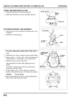
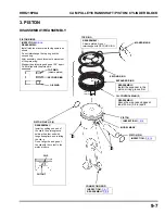
1. Apply oil to the inner wall of the cylinder and
to the outer surface of the piston.
2. Install the piston assembly in the cylinder so that the model
mark (for example: ZL8 or Z8B) by the piston pin hole and
the longer side of the connecting rod big end are at the
right side. (The crankshaft must be at the top dead center
of the compression stroke.)
The model mark on the piston must be positioned toward
the oil pan.
NOTICE
Take care not to break the piston ring when installing the
piston assembly in the cylinder.
3. Apply clean engine oil to the cylinder block crankshaft
bearing area, and install the crankshaft in the cylinder
block.
4. Apply oil to the connecting rod big end bearing and the
crank pin; then connect the connecting rod to the crank pin.
5. Apply oil to the connecting rod cap bearing.
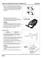
6. Install so that the projection by the oil dipper and the
projection of the connecting rod face in the same direction.
Note that the oil dipper must be on the right- hand side at
this time.
7. Tighten the connecting rod bolts to the specified torque.
TORQUE:
12 N•m (9 ft-lb)
RECESS
MODEL MARK
CONNECTING
ROD WITH THE
LONG END
OIL DIPPER
PROJECTIONS
Содержание HRR216PKA
Страница 5: ...iv HRR216PKA NOTES...
Страница 9: ...SPECIFICATIONS HRR216PKA 1 4 NOTES...
Страница 45: ...MUFFLER HRR216PKA 5 2 NOTES...
Страница 49: ...RECOIL STARTER HRR216PKA 6 4 NOTES...
Страница 63: ...FUEL SYSTEM HRR216PKA 7 14 NOTES...

