background image

HANDLE PIPE

HRR216PKA

10-6

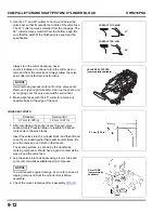
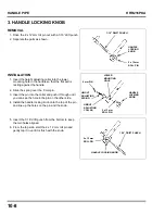
7. Remove the rear wheel bolt, wheel, wheel washer, 

and flat washer on each side.

8. Remove the split pin from each side of the axle shaft.

9. Remove the 25 mm circlip from each side, and slide 

them and the 25 mm washers inward towards the 
transmission.

10. Remove the adjuster assembly from each side, 

taking care not to damage the seals.

.

11. Remove the handle stay(s) by loosening the four 

8 mm flange nuts.

If removing the left-hand side handle stay, do not 
remove the forward-most nut that attaches the Smart 
Drive cable bracket onto the mower deck. Only the 
rearward nut needs to be removed from the Smart 
Drive cable bracket.

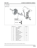
FLAT WASHER

WHEEL WASHER

WHEEL 
BOLT

SPLIT PIN

25 mm 
WASHER

25 mm 
CIRCLIP

ADJUSTER 
ASSEMBLY

8 mm FLANGE 
BOLT (4)

HANDLE STAY

Содержание HRR216PKA

Страница 1: ...thing and using safety equipment When performing any service task be especially careful of the following Read all of the instructions before you begin and make sure you have the tools the replacement...

Страница 2: ...fety messages and other safety information throughout this manual Of course it is not practical or possible to warn you about all the hazards associated with servicing these mowers You must use your o...

Страница 3: ...000001 1140000 Engine GJARA 1000001 4840000 Engine model prefix changed from GJAPA to GJARA 2 Position Clip Director No Mulching Plug New MicroCut blades Rear scroll and belt cover changed from steel...

Страница 4: ...i K11 Frame MZCG 1660001 1999999 Engine GJATA 1000001 9999999 Engine serial number prefix changed from GJARA to GJATA Otherwise identical to K10 model VERSION SERIAL NUMBERS IDENTIFIERS FEATURES CHANG...

Страница 5: ...iv HRR216PKA NOTES...

Страница 6: ...3 cu ft 17 US gal Fuel tank capacity 0 93 L 0 25 US gal Engine oil capacity 0 50 L 17 oz Refill Capacity 0 35 0 4 L 12 0 13 5 oz Engine model GCV160LA0 Engine type 4 stroke overhead cam single cylind...

Страница 7: ...Cutting height set to 28 mm 1 1 8 in 582 mm 22 9 in K8 K9 507 mm 20 0 in K10 K11 510 mm 20 1 in K8 K9 491 mm 19 3 in K10 K11 492 mm 19 4 in K8 K9 1 534 mm 60 4 in K10 K11 1 512 mm 59 5 in 620 mm 24 4...

Страница 8: ...HRR216PKA SPECIFICATIONS 1 3 3 WIRING DIAGRAM UNIT Black SPARK PLUG IGNITION COIL ENGINE STOP SWITCH NORMALLY CLOSED ENGINE SWITCH CONTACT RUN OPEN STOP CLOSE...

Страница 9: ...SPECIFICATIONS HRR216PKA 1 4 NOTES...

Страница 10: ...ly After reassembly check parts installation and operation 2 SYMBOLS USED IN THIS MANUAL As you read this manual you may find the following symbols with the instructions 1 SERVICE RULES 2 1 2 SYMBOLS...

Страница 11: ...g parts and when making technical inquiries The frame serial number is located at the center rear of the deck AMERICAN HONDA MOTOR CO INC ALPHARETTA GA 30005 8847 HRR2169PKA XX MZCG XXXXXXX American H...

Страница 12: ...6 0 0018 in 0 20 0 35 mm 0 008 0 014 in 0 35 0 50 mm 0 014 0 020 in 0 20 0 70 mm 0 008 0 030 in 0 91 mm 0 035 in 0 95 mm 0 037 in 2 37 mm 0 093 in 0 150 mm 0 006 in 0 150 mm 0 006 in 0 150 mm 0 006 in...

Страница 13: ...0 ST 12 1 2 8 7 Engine stop switch assembly M4 x 0 7 1 6 0 16 1 18 Fan cover stud bolt M6 x 1 0 12 1 2 8 7 Flywheel nut M14 x 1 5 52 5 3 38 Fuel valve bracket screw M5 x 0 6 4 5 0 45 2 2 Governor arm...

Страница 14: ...ION 1 Carburetor float level gauge 07401 0010000 Carburetor float level inspection 2 Valve adjustment wrench 3 mm 07908 KE90200 Valve clearance adjustment 3 Multi use flywheel holder 07APB Z28A100 Fly...

Страница 15: ...2 Compression gauge SUN EEP V303A Compression test 3 Flywheel puller OTC 1035 Flywheel removal 4 Combustion cleaning brush Procured locally Clean combustion chamber 5 Digital multimeter FLU 88 Electri...

Страница 16: ...ark No or weak spark NORMAL COMPRESSION Compression is high 80 psi Install a compression gauge in the spark plug hole P 2 10 and crank the engine several times Install the spark plug in the plug cap a...

Страница 17: ...r weak spark NORMAL COMPRESSION Compression is high 80 psi Install a compression gauge in the spark plug hole P 2 10 and crank the engine several times Install the spark plug in the plug cap and perfo...

Страница 18: ...hanical damage such as a bent crankshaft Grass and debris lodged under mower deck No No No No Yes Yes Yes Yes Yes Repair or replace the cable Correct as required P 8 1 Replace flywheel brake pad P 8 1...

Страница 19: ...f the compression measures above 80 psi The engine must be completely cool before proceeding 1 Remove the recoil starter P 6 1 2 If there is gasoline in the fuel tank drain it into an approved contain...

Страница 20: ...more than 80 psi and the valve clearance measurement is less than or equal to 0 24 mm 0 0094 in 1 Rotate the flywheel until the cam pulley decompressor weight slot faces out 2 Carefully inspect the we...

Страница 21: ...ulley lobe facing out remove the exhaust rocker pin and rocker arm 3 Closely inspect the rocker arm for cracks and damage Inspect the rocker pin for excessive wear or grooves If the rocker arm is dama...

Страница 22: ...haust rocker arm above the pivot pin in location A shown in step 7 9 Push and hold the tappet screw against the exhaust valve 10 While holding the tappet screw against the valve maintain zero valve la...

Страница 23: ...3 Apply Hondabond HT ThreeBond 1216 Loctite 5900 or equivalent to a new cylinder head cover in the areas shown Assemble within 10 minutes after applying the liquid gasket Tighten the head cover bolts...

Страница 24: ...4 Attach the dial indicator magnetic base to the lower deck surface 5 Position the tip of the dial indicator perpendicular and 5 10 mm 0 20 0 39 in from the end of the crankshaft 6 Zero the dial indic...

Страница 25: ...open smoothly and snap closed when released Replace the carburetor assembly P 7 1 and the spark plug P 3 8 Opens too slowly or does not open Hard to move Closed Check that the choke control assembly i...

Страница 26: ...the auto choke assembly does not return smoothly it must be replaced ENGINE STOP SWITCH INSPECTION 1 Remove the fan cover 2 Disconnect the engine stop switch connector from the ignition coil primary...

Страница 27: ...APPROVED MANNER Directions Step 1 Add water to the water line Step 2 Add gasoline to the gasoline line Step 3 Replace cap and shake vigorously Step 4 Stand vial vertically with cap upright Let stand f...

Страница 28: ...K AND FILTER 3 9 12 FLYWHEEL BRAKE 3 10 13 VALVE CLEARANCE 3 11 14 GOVERNOR 3 13 Item Action Before each use 5 hours of use or first month First 25 hours of use 50 hours of use or every 6 months 100 h...

Страница 29: ...aged or deteriorated 3 10 Valve clearance cold Intake 0 15 0 04 mm Exhaust 0 20 0 04 mm 3 11 Governor arm Adjust so shaft is rotated fully clockwise at full throttle Check engine rpm after adjusting 3...

Страница 30: ...r is tilted 2 Disconnect the spark plug cap 3 Tilt the mower on its right side so the carburetor is up 4 Inspect the blades for damage cracks and excessive wear rust or corrosion 5 Verify the blade bo...

Страница 31: ...file the upper surface of the blades only The cutting edge must be even with the lower surface of the blades Taper the blade profile removing material from the blade tip never the inner end of the cu...

Страница 32: ...or any signs of damage If they are damaged they must be replaced 2 Install the blades using the two blade bolts and special washers as shown Install the special washers with the concave side toward th...

Страница 33: ...ded oil to the upper limit mark on the dipstick Check the oil level with the mower on a level surface and the dipstick fully inserted but not screwed in Oil is a major factor affecting performance and...

Страница 34: ...surface to remove dirt or blow with compressed air not exceeding 207 kPa 30 psi through the filter from the inside Never try to brush off dirt brushing will force dirt into the fibers 5 Wipe dirt fro...

Страница 35: ...ft lb NOTICE A loose spark plug can overheat and damage the engine Overtightening can damage the threads in the cylinder head 10 SPARK ARRESTER CLEANING OPTIONAL PART The spark arrester must be servi...

Страница 36: ...Remove the fuel strainer from the fuel tube 7 Inspect the fuel strainer for sediment and other foreign material Inspect for tears or other damage 8 Wash with solvent to clean and dry thoroughly before...

Страница 37: ...he thickness of the brake shoe 4 If brake shoe thickness is less than the service limit replace the flywheel brake shoe FLYWHEEL BRAKE CABLE INSPECTION 1 Start the engine outdoors 2 Release the flywhe...

Страница 38: ...cylinder head cover by prying slowly at each corner Discard the head cover and replace it with a new one 5 Rotate the engine until the cam lobe is pointing directly forward away from the flywheel K8...

Страница 39: ...N m 5 8 ft lb d Recheck valve clearance after tightening the lock nut 8 Thoroughly clean the old sealant from the cylinder head surface using an abrasive cloth and brake cleaner 9 Apply liquid gasket...

Страница 40: ...an assistant hold the flywheel brake lever while you perform the maximum engine speed adjustment 7 Check the maximum engine speed 8 If adjustment is necessary bend the governor spring tab on the fuel...

Страница 41: ...ing at normal operating temperature push the governor arm toward the carburetor and hold it in this position 2 Adjust the throttle stop screw to obtain the specified idle speed Note The K9 K11 models...

Страница 42: ...el brake cable from the engine 5 Remove the blades 6 Remove the 3 8 24 x 1 flange bolt and remove the blade holder and Woodruff key from the crankshaft 7 Support the engine remove the four 5 16 24 x 1...

Страница 43: ...Be sure the Woodruff key remains in place when installing 3 Attach the blade holder using the 3 8 24 x 1 flange bolt TORQUE 49 59 N m 36 43 ft lbs 4 Attach the blades using the two special bolts and...

Страница 44: ...ime the muffler has been removed SPARK ARRESTER optional part INSTALLATION Install after removing the carbon from the screen with a wire brush MUFFLER INSTALLATION Use a plastic hammer to loosen carbo...

Страница 45: ...MUFFLER HRR216PKA 5 2 NOTES...

Страница 46: ...starter rope is frayed or worn out replace the starter rope P 6 2 Do not disassemble the recoil starter assembly 1 REMOVAL INSTALLATION 6 1 2 STARTER ROPE REPLACEMENT 6 2 RECOIL STARTER ASSEMBLY 6 mm...

Страница 47: ...r reel side and remove the starter rope 4 Pass the new starter rope through the starter grip and make a knot at the end of the rope 5 Pass the other end of the starter rope through the rope hole in th...

Страница 48: ...ake a knot at the end of the rope 3 Pass the other end of the starter rope through the rope hole in the starter case and through the rope hole in the starter reel and make a slipknot at the end of the...

Страница 49: ...RECOIL STARTER HRR216PKA 6 4 NOTES...

Страница 50: ...e stud 5 While pushing the air cleaner case toward the engine remove the other 6 x 86 mm bolt and temporarily install another 6 x 83 mm stud 6 Pull the breather tube from the engine and then remove th...

Страница 51: ...from the carburetor THROTTLE RETURN SPRING INSTALLATION P 7 9 GOVERNOR ROD INSTALLATION P 7 9 INSULATOR GASKET Replace CHOKE CONTROL ASSEMBLY TROUBLESHOOTING P 2 16 INSTALLATION P 2 16 CARBURETOR GASK...

Страница 52: ...1 REASSEMBLY Clean thoroughly with compressed air before installation FLOAT PIN FLOAT VALVE REASSEMBLY Check for worn float valve seat and float valve before installation FLOAT VALVE REPLACE OK FLOAT...

Страница 53: ...ng tip cleaning needle NOTICE Using a welding tip cleaning needle or a jet needle that is too large may damage the carburetor Never force a needle and never use a needle with a bent or damaged tip Ins...

Страница 54: ...bore for contamination 7 Clean the pilot jet thoroughly by using the appropriate size jet cleaning tool carburetor cleaner and compressed air The passage is small and easily obstructed so repeat sever...

Страница 55: ...nsition ports 12 Reassemble the carburetor FLOAT LEVEL HEIGHT INSPECTION Place the carburetor in the position as shown and measure the distance between the float top and the carburetor body when the f...

Страница 56: ...ly from the back of the cavity Thermowax Installation The thermowax plunger MUST be fully retracted and the overall length of the thermowax must be no more than 23 mm before installation If the thermo...

Страница 57: ...peration page 2 17 5 Verify that the carburetor choke lever is in the fully closed position 6 Install the carburetor and choke assembly page 7 2 6 After installation verify that there is clearance bet...

Страница 58: ...all the governor rod through the throttle return spring as shown Connect each to the governor arm and carburetor throttle arm as shown LONG END THROTTLE THROTTLE ARM GOVERNOR ROD GOVERNOR ARM THROTTLE...

Страница 59: ...handling fuel Stop the engine and let it cool Keep heat sparks and flame away Handle fuel only outdoors Wipe up spills immediately FAN COVER INSTALLATION Check that the high tension cord and the stop...

Страница 60: ...or seriously injured when handling fuel Stop the engine and let it cool Keep heat sparks and flame away Handle fuel only outdoors Wipe up spills immediately FAN COVER INSTALLATION Check that the high...

Страница 61: ...or other tool when removing the fuel tube NOTICE If the fuel tube is pried off the fuel valve with a tool the fuel valve may be damaged 4 Connect the fuel tube to the fuel valve Use the correct low p...

Страница 62: ...ressure in the fuel tank decreases because of low ambient temperature or consumption of gasoline the air drawn through the canister releases the stored gasoline vapor from the charcoal The released ga...

Страница 63: ...FUEL SYSTEM HRR216PKA 7 14 NOTES...

Страница 64: ...SSEMBLY Check for cracked or damaged insulation replace the coil if necessary BRAKE LEVER SPRING 6 x 23 mm FLANGE BOLT 6 x 14 mm FLANGE BOLT 12 N m 8 9 ft lb 14 x 1 5 mm SPECIAL NUT REMOVAL AND INSTAL...

Страница 65: ...BOLT 6 x 14 mm FLANGE BOLT 12 N m 8 9 ft lb 14 x 1 5 mm SPECIAL NUT REMOVAL AND INSTALLATION P 8 3 TORQUE 52N m 38 ft lb FLYWHEEL INSTALLATION P 8 5 Use caution during disassembly and reassembly to pr...

Страница 66: ...or equivalent material This allows the flywheel and crankshaft to turn 3 Hold the flywheel with the special tool and a breaker bar and remove the 14 mm special nut with a wrench NOTICE Inserting a ro...

Страница 67: ...f the puller jaws under the magnets at the PULLER mark Set a shop towel or equivalent cloth between the flywheel and the puller 6 Tighten the flywheel puller and then tap the end of the puller to remo...

Страница 68: ...n the magnets 3 Be sure the woodruff key is set in the keyway properly 4 Install the flywheel 5 Apply oil to the threads 6 Hold the flywheel with the special tool and tighten the 14 mm special nut wit...

Страница 69: ...il if either of the above tests is out of specification AIR GAP ADJUSTMENT Adjustment is required only when the ignition charge coil or the flywheel has been removed 1 Loosen the ignition charge coil...

Страница 70: ...1 9 mm Replace INTAKE ROCKER ARM INSPECTION P 9 15 VALVE ADJUSTING LOCK NUT 2 7 8 N m 5 8 ft lb CAM PULLEY DECOMPRESSOR WEIGHT INSPECTION P 9 2 INSTALLATION P 9 2 Take care not to drop the cam pulley...

Страница 71: ...leasing Repeat several times If the weight fails to completely return on its own at any time by spring force replace the cam pulley see Cam Pulley Installation below CAM PULLEY INSTALLATION 1 Turn the...

Страница 72: ...the cam pulley as shown CYLINDER HEAD COVER INSTALLATION 1 Clean the mating surface of the cylinder block using a de greasing cleaning agent and a clean shop towel 2 Apply liquid gasket Hondabond HT...

Страница 73: ...ION P 9 10 Apply grease to the lips 28 x 41 25 x 6 mm OIL SEAL INSTALLATION Be careful not to damage the lip of the oil seal when installing the oil pan with the oil seal TIMING BELT INSTALLATION Chec...

Страница 74: ...er side of the connecting rod big end are at the right side The crankshaft must be at the top dead center of the compression stroke The model mark on the piston must be positioned toward the oil pan N...

Страница 75: ...cylinder block 5 Apply a bead 1 5 2 0 mm 0 06 0 08 in of liquid gasket Hondabond HT or Loctite 5900 to the cylinder block 6 Install the oil pan on the cylinder block Assemble within 10 minutes after a...

Страница 76: ...hown Do not interchange the top ring and the second ring After assembly check for smooth movement of the piston ring Stagger the piston ring end gaps 120 apart Do not align with the piston pin SECOND...

Страница 77: ...e piston points down 3 Set the connecting rod in the piston so that the model mark by the piston pin hole and the longer side of the connecting rod large face to the right hand side 4 Apply oil to the...

Страница 78: ...sits and inspect the valve INSPECTION P 9 20 INTAKE VALVE REASSEMBLY Do not interchange with the exhaust valve VALVE HEAD DIAMETER IN 25 mm 0 98 in EX 24 mm 0 94 in INSPECTION P 9 20 VALVE SPRING 2 IN...

Страница 79: ...ning of the combustion chamber Do not press the cleaning brush with force against the combustion chamber VALVE SEAT RECONDITIONING Valve Seat Inspection 1 Thoroughly clean the combustion chambers and...

Страница 80: ...er into the cylinder to protect the cylinder wall during valve seat reconditioning 60 45 31 VALVE SEAT CUTTER SOLID PILOT BAR 5 50 mm NWY PM 100055SH SOLID PILOT BAR 5 51 mm NWY PM 100552S VALVE SEAT...

Страница 81: ...remove any possible burrs at the edge of the seat VALVE SEAT WIDTH 1 After resurfacing the seats inspect for even valve seating Apply Prussian Blue or erasable felt tipped marker ink to the valve fac...

Страница 82: ...LY Before installing check for wear and damage of the gear Check that the weights move freely Be sure to install the governor weight before installing the crankshaft 8 mm LOCK PIN REASSEMBLY Install t...

Страница 83: ...PECTION Inspect the decompressor return spring for proper strength Check the decompressor arm and pin for proper movement and wear P 2 11 CAM PULLEY SHAFT O D INSPECTION Standard Service limit 37 394...

Страница 84: ...is worn beyond the service limit it must be replaced Do not hone the cylinder 2 Measure and record the Piston O D at a point 10 mm 0 4 in from the bottom of the skirt and 90 to the piston pin bore 3...

Страница 85: ...0 93 0 95 mm 0 036 0 037 in 0 91 mm 0 035 in Second ring 0 97 0 99 mm 0 038 0 039 in 0 95 mm 0 037 in Standard Service limit Top ring 0 055 0 089 mm 0 002 0 004 in 0 150 mm 0 006 in Second ring 0 015...

Страница 86: ...ANKSHAFT MAIN JOURNAL O D INSPECTION Standard Service limit 13 002 mm 0 5119 in 13 048 mm 0 5137 in Standard Service limit 13 005 mm 0 5120 in 13 07 mm 0 515 in Standard Service limit 26 02 mm 1 024 i...

Страница 87: ...AXIAL CLEARANCE INSPECTION Measure the clearances with a feeler gauge CONNECTING ROD BIG END OIL CLEARANCE INSPECTION 1 Wipe oil off the crank pin and connecting rod bearing mating surface 2 Place the...

Страница 88: ...replacement OIL PAN MAIN JOURNAL I D INSPECTION Inspect the bearing surface for scoring or damage If the bearing surface is worn or damaged the oil pan and crankshaft will require replacement CRANKSHA...

Страница 89: ...VE GUIDE I D INSPECTION Measure and record each valve guide I D Replace the cylinder block if they are over the service limit VALVE SEAT WIDTH INSPECTION 1 Measure the valve seat width 2 Recondition t...

Страница 90: ...10 1 10 HANDLE PIPE 1 HANDLE PIPE REPLACEMENT 10 2 2 HANDLE STAY REMOVAL INSTALLATION 10 3 3 HANDLE LOCKING KNOB 10 8...

Страница 91: ...the handle assembly from the handle stays 6 Drive out the two 2 x 12 mm roll pins and remove the handle lock assemblies 7 Remove the 6 mm locking nut and the rope guide 8 Install the handle pipe in t...

Страница 92: ...are under tension and can fly out and injure someone 3 To replace the grass bag plate remove the three grass bag plate bolts 4 Release the handlebar locking knobs and allow the handle pipe assembly t...

Страница 93: ...the three 8 mm flange nuts and the right handle stay 10 Installation is the reverse of removal The left and right discharge guard return springs are different Position the springs so the hooks lead to...

Страница 94: ...can fly out and injure someone 3 To replace the grass bag plate remove the three grass bag plate bolts Removal of the grass bag plate is not required for handle stay removal 4 Release the handlebar lo...

Страница 95: ...the adjuster assembly from each side taking care not to damage the seals 11 Remove the handle stay s by loosening the four 8 mm flange nuts If removing the left hand side handle stay do not remove the...

Страница 96: ...discharge guard return springs are different Position the springs so the hooks lead to the underside of the spring Apply pressure to hold the springs in place while installing the discharge guard shaf...

Страница 97: ...through until you can see the hole in the pin on the other side 4 Install the handle locking knob onto the top of the pin and line up the holes on the pin and the knob 5 Insert the 1 16 drift punch fr...

Страница 98: ...tends to pop apart when removed 4 Remove the three 6 x 10 mm flange bolts 1 two 6 x 8 mm shoulder bolts 2 and one shoulder screw 3 and remove the rear scroll 5 Remove the Clip Director door through th...

Страница 99: ...5 16 24X1 4 5 Front scroll 1 21 Push nut 7 94 mm 1 6 Rear scroll 1 22 Nylon locknut 8 mm 1 7 Rear shield shaft 1 23 Plain washer 5 16 2 8 Scroll plate 1 24 Flange nut 8 mm 2 9 Guide plate 1 25 Flange...

Страница 100: ...late bolt 3 7 Special bolt 6 x 12 5 3 23 Flange nut 6 mm 3 8 Cutter housing 1 24 Grass bag plate 1 9 Front scroll 1 25 Rear shield 1 10 Plain washer 5 16 2 26 Flat round push nut 3 96 mm 1 11 Flange n...

Страница 101: ...on Quantity Wheel shaft bolt 2 Wheel bearing 4 Wheel 2 Wheel washer 2 Rear adjuster collar 2 Right left rear adjuster arm 1 each Rear adjuster plate 2 Adjuster grip 2 Right left rear adjuster panel 1...

Страница 102: ...antity Wheel shaft bolt 2 Wheel bearing 4 Wheel 2 Wheel washer 2 Rear adjuster collar 2 Right left rear adjuster arm 1 each Rear adjuster plate 2 Adjuster grip 2 Right left handle stay 1 each Flat was...

Страница 103: ...ntity Front wheel shaft bolt 2 Wheel washer 2 Front wheel 2 Adjuster arm bolt 2 Front adjuster plate 2 Adjuster grip 2 Right left front adjuster arm 1 each Front adjusting collar 2 Front adjuster pane...

Страница 104: ...Fan cover removal installation K8 7 10 Fan cover removal installation K9 K11 7 11 Filter air 3 7 Flywheel Installation 8 5 Removal 8 3 Flywheel brake inspection 3 10 Fuel cap 7 13 Fuel strainer 7 10...

Страница 105: ...park plug Inspection cleaning 3 8 Test 2 15 Special tools 2 5 Specifications Dimensions weight capacities 1 1 Engine 1 1 Maintenance 3 2 Service 2 3 Tune up 3 2 Stop switch 8 5 Stop switch inspection...

Отзывы: