Hommax Sistemas DS-8104HMI-M SERIES Скачать руководство пользователя страница 15

User Manual of DS-8104HMI-M(/XX) Series Mobile Net DVR (V1.20.00) 

- 15 - 

Note: Please contact the vehicle battery manufacture for the information on the voltage polarity. 


2.5.2


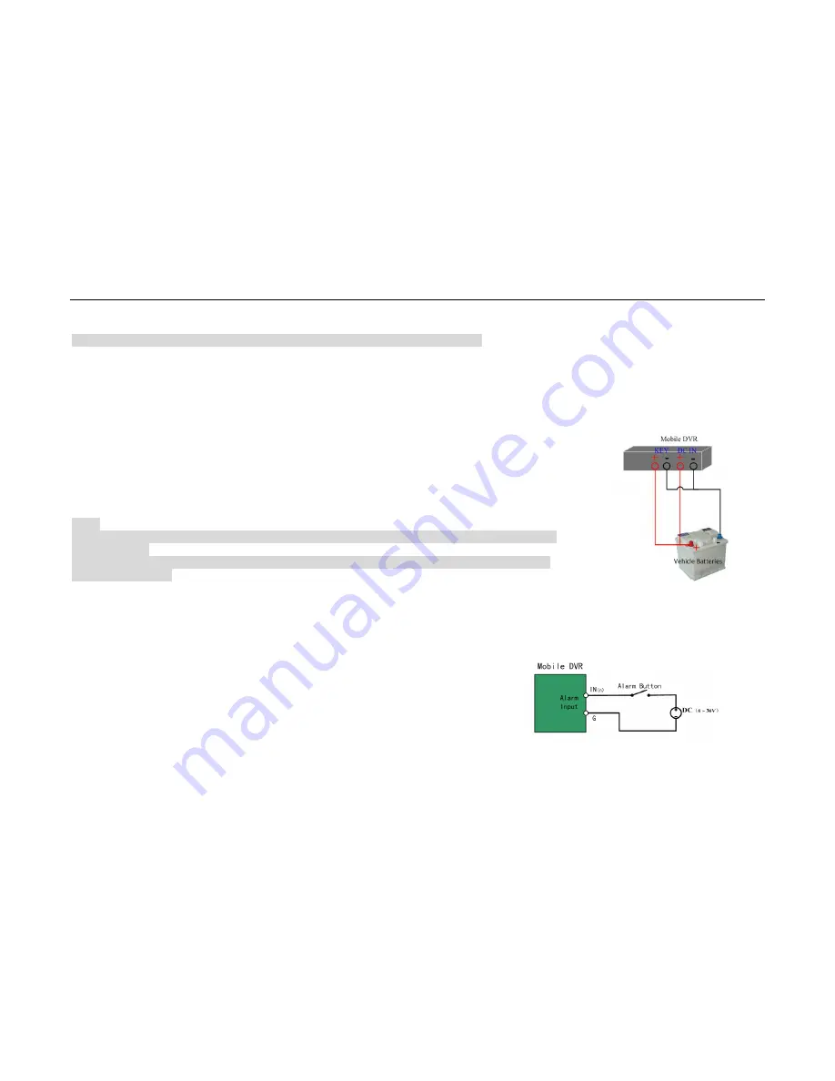
  Connection for auto power on-off 

Connect DC+ and KEY+ to the vehicle batteries positive pole and DC- and KEY- to the vehicle 
batteries negative pole for the DVR auto on-off function. 

The connection is as Fig 2.10.


The settings 

details please refer to section 5.8.1. 
 
DS-8104HMI-M (/XX) series mobile DVR working consumption is less than 10W. If you need a long 
auto working time, please considering standby power supply according to the conditions.     
 

Note:   
1. When testing the DVR, please refer to the power connection. When the basic two power on conditions are met, 
the DVR will work. 
2.To make sure the DVR can power on normally, the power consumption should be more than 36W, the working 
voltage is DC 6V to 36V. 


2.6


Alarm Output Connection Guide 

Alarm Input connection: 

DS-8104HMI-M(/XX) series mobile DVR is applied high and low level signal to trigger the alarm input. 
DC 0V to 5V is low level signal, DC 6V to 36V is high level signal. To avoid misidentification, signal 
between DC 5V to 6V will not be handled. 
The alarm input connection is as Fig 2.11: 


Fig 2.10 KEY connect with vehicle batteries 


Fig 2.11 Alarm Input Connection 

Содержание DS-8104HMI-M SERIES

Страница 1: ...User Manual of DS 8104HMI M XX Series Mobile Net DVR V1 20 00 1 DS 8104HMI M XX Embedded Mobile Net DVR User Manual V1 20 00...

Страница 2: ...rsion The listed products or programs will be improved or renewed whenever necessary Tips for users Please install the DVR in well ventilated places Please make sure the DVR work in the allowed range...

Страница 3: ...SIM UIM Installation 12 2 5 KEY Ignition Switch Connection 13 2 5 1 Connection for Time Delay Shutdown 14 2 5 2 Connection for auto power on off 15 2 6 Alarm Output Connection Guide 15 3 Operation Gu...

Страница 4: ...34 5 2 Local Preview Setup 35 5 2 1 Video output standard 35 5 2 2 Screen Saver Setup 35 5 2 3 OSD Setup 35 5 2 4 Video Parameters Setup 36 5 2 5 Mask Area Setup 36 5 2 6 Preview Properties 37 5 3 Al...

Страница 5: ...P settings 50 5 8 4 Server Login Setup 50 6 Utilities 52 6 1 Save Parameters 52 6 2 Restore Parameters 52 6 3 Upgrade 53 6 4 SD Card 53 6 5 Clear Alarm Out 54 6 6 Reboot 54 6 7 Power Off 54 6 8 View L...

Страница 6: ...fans and be prevented from dust water and rust Key features Support SD storage Build in 3G wireless network module Support GPS Support shutdown delay and auto power on off Support ignition power on a...

Страница 7: ...hoice of playback modes fast forward slow forward and single frame Search by recording type and time Indication of recording and alarm status Alarm Support speed limit alarm 7 ch level signal alarm in...

Страница 8: ...s Mobile Net DVR V1 20 00 8 Audio preview and screen capture at client software PPP enabled Client developing Network protocol provided for platform system development SDK provided for client developm...

Страница 9: ...according to the list inside once you get it 2 2 Interface Description DS 8104HMI M XX front panel is shown as below Note the descriptions are subject to the physical product No Interface Description...

Страница 10: ...D card socket 3 USB Connect to USB devices support USB 2 0 4 LAN Connect to ETHERNET devices 5 DEBUG Device debug port connect with special cable in accessories box 6 SIM UIM SIM UIM card socket the y...

Страница 11: ...or power on should be more than 36W 3 In J3 interface alarm inputs 1 to 7 are level signal and alarm input 8 is pulsing signal Detail description for aviation jack 4 J1 Video Audio input output J2 Dc...

Страница 12: ...4 4 With the default configuration the corresponding recording times for different Volume are SD volume Unit GB Recording time Bit Rate 512Kbps Unit Hour Recording time Bit Rate 1Mbps Unit Hour Record...

Страница 13: ...icle battery and KEY to ignition switch or batteries the details please refer to the below connection figures 2 Please make sure that the positive pole of DVR power line connects the positive pole of...

Страница 14: ...o the vehicle ignition switch Connect the GND and KEY of DVR to the negative pole of vehicle batteries 2 Connection of Negative Pole Switch Fig 2 9 Connect the DC IN and KEY of DVR to the positive pol...

Страница 15: ...ease considering standby power supply according to the conditions Note 1 When testing the DVR please refer to the power connection When the basic two power on conditions are met the DVR will work 2 To...

Страница 16: ...T and GND will be connected status that means user must connect alarm device with power supply The alarm output connection is as Fig 2 12 Connection Description Detailed steps are as below 1 Pull out...

Страница 17: ...racter 4 EDIT 1 Enter the edit state and then delete the character in the front of the cursor 2 Switch between and in the status box 5 A 1 Switch between input methods Number English Chinese Symbol 2...

Страница 18: ...and selecting the data items by press 2 PTZ Position Control 3 Playback fast slow forward and rewind ENTER 1 Confirm when in menu mode 2 Switch between and in the status box 3 Pause when playback 13 P...

Страница 19: ...ording Stream Type Resolution Bit Rate Type Max Bit Rate Image Quality Frame Rate Enable Recording Pre Recording Time Post Recording Time Copy to Camera Network Basic network parameters e g IP Mac Mul...

Страница 20: ...back interface Press REC button to enter the manual record interface Press PTZ button to enter the PTZ control interface Note Password is required and the default user name is admin password is 12345...

Страница 21: ...ere is a small rectangular frame named Active Frame which is pointing to the selected item This Active Frame can be moved by or keys There are such kinds of menu items a Check Box Provide 2 options me...

Страница 22: ...bottom of the screen you can input the characters in the edit box by pressing Numeric Keys on the IR control If you want to input English i e uppercase just switch the input method to Uppercase by pre...

Страница 23: ...f DVR so as to operate the device with the visible menu After power on and switch on the ignition the device begin to start up the POWER indicator is turn green When Ready turn green means this device...

Страница 24: ...te No Video White Video Lost Yellow Video Input Yellow View Tampering Pink Manual Recording Pink Motion Detection Sensor Alarm Green Schedule Recording Green No Alarm Blue Motion Detection Recording B...

Страница 25: ...ord for the users created by admin For example a user named user The method of adding and deleting user please refer to section 5 1 2 please modify the password as follow Step 1 Enter the main menu an...

Страница 26: ...key PLAY AUTO Exit the PTZ control operation menu If you want to do the other operation such as playback manual record and so on you need to exit the PTZ operation menu Press the ESC button to exit an...

Страница 27: ...to exit manual record and enter preview mode Press MENU key to enter main menu Press Play key to enter into playback menu Press PTZ key to enter PTZ control mode 4 6 Playback Note The user must have P...

Страница 28: ...ume Play Process Play Speed Played Time and File Total Time Fig 4 8 Playback control keys description Display Hide information bar MENU Open Close sound PLAY under the mute mode will appear on the bar...

Страница 29: ...ments when the image is being playback The steps are as follow Step 1 Enter the interface of playback the files or playback by time Step 2 Press EDIT key to start selecting the current playback image...

Страница 30: ...ack and download recorded files The details please refer to the user manual of MVA 4 7 3 Backup File Playback Backup files naming rule Backup files will be saved in the file named with the DVR name Pl...

Страница 31: ...User Manual of DS 8104HMI M XX Series Mobile Net DVR V1 20 00 31...

Страница 32: ...hedule External alarm sensor type View tampering alarm schedule Video lost alarm schedule Motion detection alarm schedule External alarm schedule Login server parameters Wireless network parameters 5...

Страница 33: ...password in the Display menu Fig 5 6 Setting the Require Password status as Note For security reason it is better for you to set Require Password as after completing all the setup 5 1 2 Add and Delet...

Страница 34: ...nt channel function Preview Network live preview Playback Remote playback download the recorded files on DVR MAC address This MAC address is not the address of DVR but the PC that will access DVR If y...

Страница 35: ...L or NTSC video output The video input standard is adaptive You can modify video output standard to match video input in Display menu 5 2 2 Screen Saver Setup If the user operates nothing for a period...

Страница 36: ...e is Position button you can setup camera name position by pressing this button You can copy the position to any other camera but please note that camera s name can not be copied 5 2 4 Video Parameter...

Страница 37: ...ask area The maximum mask area is the full screen and the minimum size is only one pane You can setup 4 mask areas at most Press A key to clear all mask areas Note The mask areas can not be copied to...

Страница 38: ...n preview mode 10s alarm display delay time DVR will display 4 channels when there is an alarm from camera 1 the screen will switch to camera 1 after 10 seconds Preview layout setup There is a square...

Страница 39: ...r camera Recording please refer to section 5 4 PTZ linkage order is Alarm in Trigger camera PTZ PTZ linkage can be setup in Alarms and PTZ Linkage interfaces Fig 5 13 Please make sure the camera has a...

Страница 40: ...alarm output schedule by entering Schedule menu from Alarms interface Fig 5 14 5 3 2 Motion Detection Alarm Motion Detection Alarm setup includes motion detection area schedule and policy In Image Se...

Страница 41: ...motion areas A Save and return Image Setup menu ENTER Cancel setup and return Image Setup menu ESC Motion alarm policy Fig 5 16 1 Motion alarm schedule You can setup it in Motion Det Policy menu The...

Страница 42: ...area setup alarm schedule and handle methods The setup can be done in Image Setup View Tampering Area and Policy The default is Off there are 3 options low Normal and High Select one of them will act...

Страница 43: ...he max bit rate selection has relations with resolution If you select high resolution you must select high bit rate For CIF resolution the typical max bit rate is 384K 768Kbps It is better to select t...

Страница 44: ...ion 5 13 3 The time period is among 00 00 24 00 5 5 Network Parameters If you want use network to access DVR you must setup network parameters Note If any network parameter is modified you must save a...

Страница 45: ...communicate in different network segments you need to set gateway 2 The bandwidth of every channel please refers to the Max bit rate setup of section 5 4 1 5 6 PTZ In PTZ menu you can setup the PTZ p...

Страница 46: ...se setup Cruise is remembering the track of PTZ movement This movement is manual controlled In PTZ menu press Setup button on the right side of Cruise item you can enter into Cruise setup menu to setu...

Страница 47: ...ress conflict network failure NTSC PAL differ and speed limit etc The parameters can be set in Exceptions menu Fig 5 25 You can choose an exception type then select the handle methods as following Aud...

Страница 48: ...modem type and parameters WVS the parameters for login the wireless remote monitoring server iVMS the parameters for login the IVMS7000 platform 5 8 1 Boot Halt Setup In the boot halt menu Fig 5 27 yo...

Страница 49: ...ing the DVR with GPS module please connect antenna correctly details please refer to section 2 3 When receiving GPS signal it starts positioning function Note To ensure the GPS module works effectivel...

Страница 50: ...ireless module please get the information of the network including APN number username and password from ISP Before parameters setup please connect antenna and keep it vertical Select the correct modu...

Страница 51: ...tatic WAN IP Port connect port between DVR and center server the default is 7660 Login id the ID assigned by the server you can get these from the iVMS7000 server Please add the ID in iVMS7000 managem...

Страница 52: ...Card Stop Alarm Out Reboot Power Off View Log and System Info The Utilities menu is shown in Fig 6 1 6 1 Save Parameters Save current parameters to device FLASH this change will take effective after...

Страница 53: ...erver Input the ftp server IP and press Enter DVR will connect with FTP server through network and download the upgrade firmware file If you select USB mode please make sure you connect one USB flash...

Страница 54: ...s per page 250 pages Also you can select options to search Search by type Type is divided into Major type and Minor type Major type includes operation alarm exception and all The operation major type...

Страница 55: ...elect By Time input start time and stop time After finish searching DVR will list the matched log information 2000 items maximum Search by type time Select By Type Time input major type minor type sta...

Страница 56: ...irement is confirmed according to Formula 2 to calculate the storage capacity i m which is storage of each channel needed unit Mbyte i m i q i h i D 2 In the formula i h The recording time for each da...

Страница 57: ...the bit rate type is FIXED for different bit rate the file size of ONE channel in ONE hour is Bit Rate Max Bit Rate File Size Bit Rate Max Bit Rate File Size Bit Rate Max Bit Rate File Size 96k 42M 32...

Страница 58: ...Use the following left side method to make the network cable when DVR is connected with network hub or switch 2 Use the following right side method to make the cross network cable when DVR is directly...

Страница 59: ...n 8Mbps MAX Audio Compression Standard OggVorbis Audio Input 1 2 ch 2 0 2 4Vp p 1000 Audio Output 1 ch 2 0 2 4Vp p 600 Stream Type Video stream or Video Audio stream Alarm Input 7 ch level input 1 ch...

Страница 60: ...er Manual of DS 8104HMI M XX Series Mobile Net DVR V1 20 00 60 Operating Temperature 10 55 Humidity 10 95 Dimensions 155mm 45mm 105mm Weight About 1Kg Device Control Special wire control for mobile DV...

Страница 61: ...n directly control the device with this remote controller by pressing MENU button The default device code is 255 If it still does not work after repeating many times Please check the reasons 1 Check t...

Страница 62: ...tact the supplier After exclude all of above reasons please change a new GPS module if it still does not work please contact the supplier Note In caves tunnels and some other environments there is no...

Отзывы: