background image

8

B

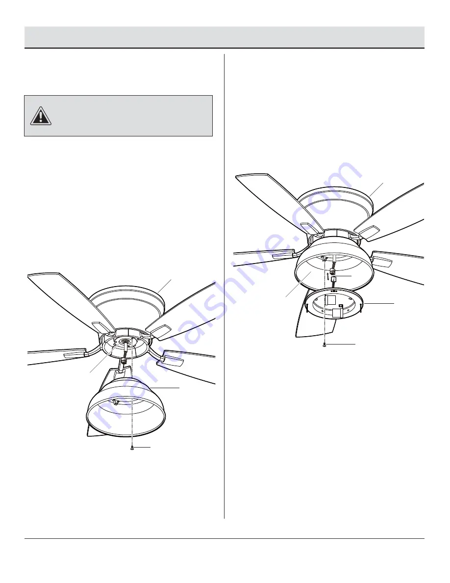
Attaching the light kit mounting 
plate to the mounting ring

     Remove one of the three light kit mounting plate 

screws (EE) from the mounting ring (KK) and loosen 
the other two screws (EE). (Do not remove)

     Place the key holes in the light kit mounting plate (F) 

over the two screws (EE) previously loosened from 
the mounting ring (KK), and turn the light kit 
mounting plate (F) until the light kit mounting plate 
(F) locks in place at the narrow section of the key 
holes. 

     Securely tighten the two light kit mounting plate 

screws (EE) previously loosened and the one (EE) 
previously removed.

EE

F

KK

CAUTION:

 Before starting installation, disconnect the 

power by turning off the circuit breaker or removing the fuse 
at the fuse box. Turning power off using the fan switch is not 
sufficient to prevent electric shock.

Assembly — Installing the Light Kit

9

Attaching the light kit to
the light kit mounting plate

     While holding the light kit (G) under the fan, snap 

together the wire connection plugs (LL).

     Carefully push all wires back into the light kit 

mounting plate (F). Install the light kit (G) onto the 
light kit mounting plate (F) with the three light kit 
mounting screws (FF) provided. Be sure to tighten all 
screws.

F

FF

G

LL

B

12

Содержание 1003 823 909

Страница 1: ... store call Home Decorators Collection Customer Service 8 a m 7 p m EST Monday Friday 9 a m 6 p m EST Saturday 1 800 986 3460 HOMEDEPOT COM HOMEDECORATORS Visual instruction of how to install this fan Visit www homedepot com and enter either the Item or Model number to find this fan and click the link of visual instruction in the product overview section ...

Страница 2: ... Included Package Contents Installation Assembly Hanging the Fan Attaching the Fan Blades Installing the Light Kit 2 3 4 4 4 4 5 6 7 8 8 11 12 READ AND SAVE THESE INSTRUCTIONS Operation Pull Chain Operating Instructions Reverse Switch Operating Instructions Care and Cleaning Troubleshooting Service Parts 14 14 14 15 15 17 ...

Страница 3: ...electrician 3 The outlet box and support structure must be securely mounted and capable of reliably supporting a minimum of 35 lbs 15 9 kg or less Use only UL listed outlet boxes marked FOR FAN SUPPORT 4 The fan must be mounted with a minimum of 7 ft 2 1m clearance from the trailing edge of the blades to the floor 5 Avoid placing objects in the path of the blades 6 To avoid personal injury or dama...

Страница 4: ...seful life when protected from varying weather conditions A certain amount of wobble is normal and should not be considered a defect Servicing performed by unauthorized persons shall render the warranty invalid There is no other express warranty We hereby disclaim any and all warranties including but not limited to those of merchantability and fitness for a particular purpose to the extent permitt...

Страница 5: ...ght kit mounting screw preassembled 9 Watt LED medium base bulb not to scale Pull chain and fob not to scale Part Part Description Description 3 4 16 10 3 3 2 2 Quantity Quantity Pre Installation continued HARDWARE INCLUDED HARDWARE INCLUDED NOTE Hardware shown to actual size unless noted otherwise in the table below 5 HOMEDEPOT COM HOMEDECORATORS Please contact 1 800 986 3460 for further assistan...

Страница 6: ...n Description Blade Light kit mounting plate Light kit Glass shade A B C F G H E D Pre Installation continued 6 Part Part A B C D Quantity Quantity 1 1 1 5 Quantity Quantity 5 1 1 1 Description Description Mounting bracket Fan motor assembly Canopy ring Blade arm ...

Страница 7: ...ing must be able to fully support the weight of the moving fan at least 35 lbs Do not use a plastic outlet box The illustrations below show two different ways to mount the outlet box II not included WARNING To reduce the risk of fire electric shock or personal injury mount the fan to an outlet box marked acceptable for fan support using the screws provided with the outlet box An outlet box commonl...

Страница 8: ...et box II Ensure the mounting bracket A is tight and secured WARNING To reduce the risk of fire electric shock or other personal injury mount the fan only to an outlet box or supporting system marked acceptable for fan support and use the mounting screws provided with the outlet box Lift the fan into position by hanging the fan motor assembly B onto the hook from the ceiling mounting bracket A all...

Страница 9: ...of the fan Connect the fan motor white wire to the supply white neutral wire using a plastic wire nut AA Connect the fan motor black wire and the blue wire to the supply black hot wire using a plastic wire nut AA Turn the wire nut connections upward spreading them apart so the green ground will be on one side of the outlet box II and the white black and blue wire will be on the other side Carefull...

Страница 10: ...cket A hook and engage the key holes with the two mounting bracket screws BB previously loosened Install the two mounting bracket screws BB previously removed and tighten all four mounting bracket screws BB Raise the canopy ring C up against the mounting bracket A The four supports inside the fan motor assembly B should be placed against the four studs on the mounting bracket A Twist the canopy ri...

Страница 11: ...the blade E is straight Repeat these steps for the remaining blades E Fastening the blade assemblies to the motor WARNING To reduce the risk of personal injury do not bend the blade arms D while installing balancing the blades E or cleaning the fan Do not insert foreign objects between rotating fan blades E Fasten the blade assemblies to the fan motor assembly B Tighten the two blade arm screws wi...

Страница 12: ...g plate screws EE previously loosened and the one EE previously removed EE F KK CAUTION Before starting installation disconnect the power by turning off the circuit breaker or removing the fuse at the fuse box Turning power off using the fan switch is not sufficient to prevent electric shock Assembly Installing the Light Kit 9 Attaching the light kit to the light kit mounting plate While holding t...

Страница 13: ... not sufficient to prevent electric shock Install the 9W LED bulb GG included Position the notches NN in the outer rim of the glass shade H so they line up with the tabs MM on the inside of the rim on the light kit G Carefully lift the glass H up inside the light kit G and secure it to the fan by turning the glass shade H clockwise until snug DO NOT OVERTIGHTEN B H GG G 13 HOMEDEPOT COM HOMEDECORA...

Страница 14: ...t kit G HH G NOTE Wait for the fan to stop before reversing the direction of the blade rotation REVERSE SWITCH OPERATING INSTRUCTIONS REVERSE SWITCH OPERATING INSTRUCTIONS Warm weather Counterclockwise Direction A downward air flow creates a cooling effect This allows you to set your air conditioner on a warmer setting without affecting your comfort Cool weather Clockwise Direction An upward air f...

Страница 15: ...the electrical panel box before you attempt any repairs Refer to step 3 Making the electrical connections on page 9 Check the main and branch circuit fuses or breakers Check the line wire connections to the fan and switch wire connections in the switch housing Make sure all motor housing screws are snug Make sure the screws that attach the fan blade arm to the motor hub are tight Make sure the wir...

Страница 16: ...iling above the tip of one of the blades Measure from a point on the center of each blade to the point on the ceiling Rotate the fan until the next blade is positioned for measurement Repeat for each blade Measurement deviations should be within 1 8 in Run the fan for ten minutes Use the enclosed blade balancing kit if the blade wobble is still noticeable The fan wobbles Troubleshooting continued ...

Страница 17: ...lastic wire nut Canopy mounting screw with lock washer preassembled Blade attachment screw and fiber washer Blade arm screw with lock washer preassembled Light kit mounting plate screw preassembled Light kit mounting screw preassembled 9 Watt LED medium base bulb Pull chain and fob Service Parts A E F G H D AA BB CC DD B C GG FF EE HH 17 HOMEDEPOT COM HOMEDECORATORS Please contact 1 800 986 3460 f...

Страница 18: ...parts Before returning to the store call Home Decorators Collection Customer Service 8 a m 7 p m EST Monday Friday 9 a m 6 p m EST Saturday 1 800 986 3460 HOMEDEPOT COM HOMEDECORATORS Retain this manual for future use YG730001 A ...

Отзывы: