


14
Sanimaster T, Sanimaster G (twin station)
The controller of Sanimaster automatically ensures an
even distribution of operating hours on both pumps by
changing the starting sequence after each pump stop.
When the liquid level in the tank reaches the start level,
one pumps is started. If the liquid level rises further, the
other pump is started as well. This pump will run until its
stop level is reached. The operating pump will stop, when
the lowest stop level is reached.
If the liquid level continues to rise when both pumps are
operating, an alarm is given until the liquid level is low-
ered below the alarm level.
3.3. Technical Data
Discharge
Saniboy I, Saniboy I R, Saniboy II, Sanimas-
ter
DN 80 with
EU-piece
DN 100
Saniboy G, Sanimaster G
BSP 2" M
Voltage
1Ph-motor (Model W)
230 V
3Ph-motor (Model D)
400 V
Speed
Saniboy/-master...W, Saniboy/-master...D,
1450 rpm
Saniboy...HD, Sanimaster...HD
2900 rpm
Saniboy G, Sanimaster G
2900 rpm
Insulation class
F
Enclosure class
Pump motor
IP 68
Control box
IP 54
Cable
Unit – control box
3,0 m
Control box - plug
0,8 m
Cable type
Unit – control box
A05RN-F...
Control box - plug
H07RN-F...
Control power consumption
15 W
Ambient temperature
0° up to 40°C
Storage temperature
-30° up to
+50°C
Noise level during operation, 1,60 m from the
ground
≤
70d(B)A
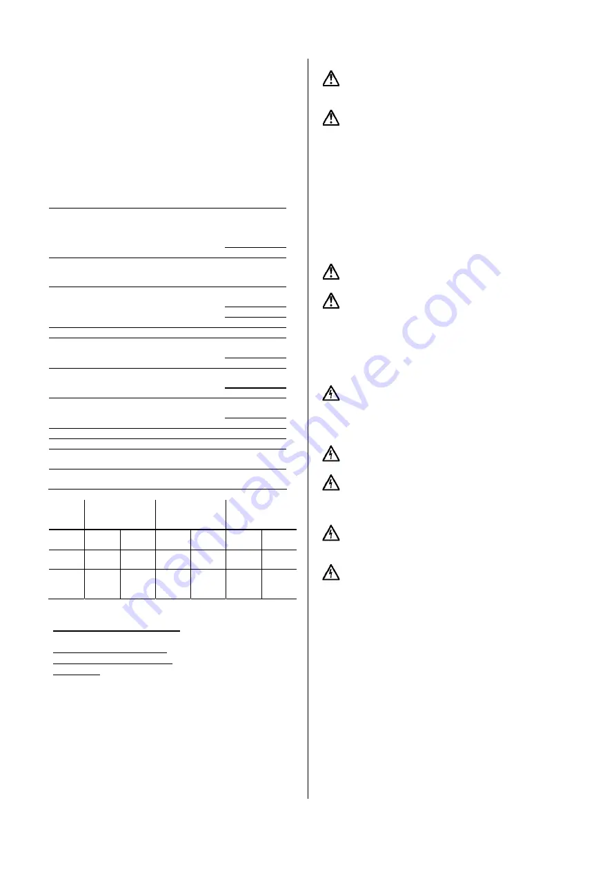
Saniboy
I,
Saniboy I R,
Saniboy II
Sanimaster
Saniboy G,
Sanimaster G
Inlet
height
180
mm
250
mm
180
mm
250
mm
180
mm
250
mm
Tank
volume
100 l
100 l
120 l
120 l
46 l
46 l
Opera-
ting
volume
45 l
70 l
65 l
100 l
24 l
31 l
3.4. Operating Conditions
Maximum liquid temperature: 35°C, short term up to
60°C.
Density of pumped liquid: max. 1100 kg/m
3
Ph-value of pumped liquid: 5 up to 11.
Operation: The motors are designed for continuous op-
eration (S1) with fully submerged motor, maximum 15
starts per hour. Our standard warranty and maintenance
regulations refer to intermittent operation. For reduced
warranty periods and service intervals due to continuous
operating conditions please contact our service depart-
ment.
3.5. Explosive Environments
For operation of the pumps in explosive environments
only models with explosion-proof motors (Ex model) must
be used.
For each individual installation the explosion classifi-
cation (Ex-class) of the pump must be approved by the
localauthorities.
4. Warranty
Our warranty only covers pumps which are installed and
operated in accordance with these installation and opera-
tion instructions and accepted codes of good practice and
being used for the applications mentioned in these in-
structions.
5. Transport and Storage
Never use the cable, the pump or the pressure com-
pensation hose to lift, lower or transport the unit.
The unit may be transported and stored in vertical or
horizontal position. Make sure that it cannot roll or fall
over. For longer periods of storage, the unit should be
protected against moisture, frost or heat.
6. Electrical Connection
6.1. General instructions
Before operation, an expert check must secure that
the required electrical protection measures exist. The
connection to ground, earthing, isolating transformer, fault
current breaker or fault voltags circuit must correspond to
the guidelines set forth by the responsible power plant.
The voltage required in the technical data sheet
must correspond to the existing line voltage.
Make sure that the electrical pin-and-socket connec-
tions are installed flood- and moisture-safe. Before start-
ing operation check the cable and the plug against dam-
ages.
The end of the pump power supply cable must not be
submerged in order to prevent water from penetrating
through the cable into the motor.
The normal separate motor starter/control box of
standard as well as of explosion proof pumps must
not be installed in explosive enviroments.
The electrical connection of the pump should be carried
out in accordance with local requirements.
The operating voltage and frequency are marked on the
pump and controller nameplates. Voltage tolerance : +6%
up to -10% of the voltage stated on the nameplates. Make
sure that the lifting station is suitable for the electricity
supply available at the installation site.
HOMA disposal units are supplied with a control box.
Controller for single-phase pumps also incorporate the
operating capacitors required.
The pump motors have a thermal switch incorporated in
the motor windings. The thermal switch protects the motor
from overheating by cutting off the supply to the pump via
the controller.
The electrical connection must be carried out in accor-
dance with the marking on the cable to the controller.
The lifting stations require no additional motor protection.
Connect the units to the mains supply.


