background image


P a g e

 | 

16


Kakute F7


Initial Configuration 

The full configuration of Betaflight could take hours to document. In this section, we’ll describe a few 
things that are specific to this board. This won’t be enough to get you into the air, so we’ll also point you 
to some videos you can watch if you’re not perfectly sure what else you need to do. Even people have a 
few builds under their belt may be skipping some important steps without realizing it! 

Connect to The Board 

Plug the board in to USB. Start Betaflight Configurator. You should see “COM3” (or some other number) 
in the upper-right menu. Click “Connect”. 


The GUI will load.  

Ports 

Click on the “Ports” tab on the left side of the window. 


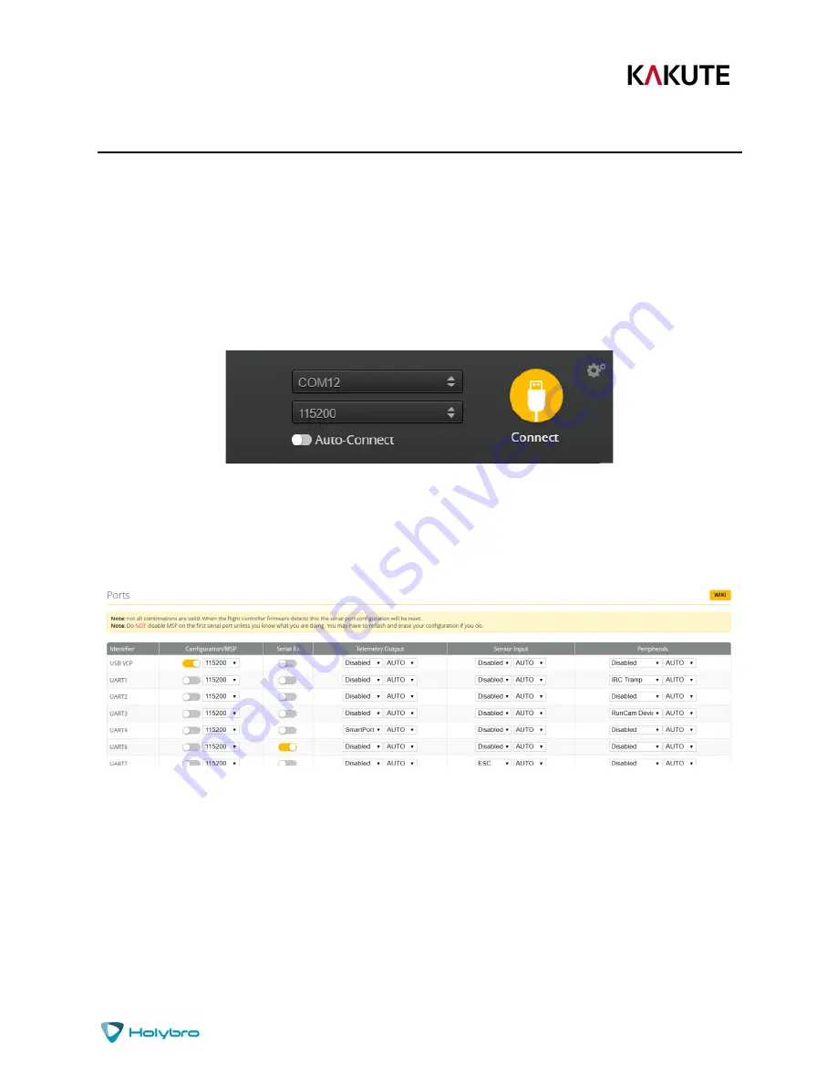
The UARTs on your Kakute F7 are versatile; any UART can be used for any function. This is different from 
the Kakute F4, in which certain functions had to be assigned to certain UARTs. In the wiring instructions 
above, certain UARTs were suggested, such as soldering the SBUS receiver to R6. However you don’t 
have to follow these recommendations if for some reason they don’t work for you. If you followed the 
instructions in this guide, the screen shot above shows how to configure the Ports tab. 

When you configure the Ports, keep the following guideline in mind: each UART can be used for one 
function only. Each column (Serial RX, Telemetry Output, Sensor Input, Peripherals) represents a single 
function. So each UART row should only have one function active at a time. If you try to enable multiple 
functions, the configuration may be rejected, or the results may be unpredictable. 

Содержание 11033

Страница 1: ...11033 Kakute F7 User Manual Installation Guide v1 0...

Страница 2: ...icy Pinout Diagram 4 Installation Guide 5 Updating Betaflight Firmware 12 Installing Drivers Installing Betaflight Configurator Flashing New Firmware Initial Configuration 16 Connect to The Board Port...

Страница 3: ...se high sensitivity IMU ICM20689 with 6 axis gyro and accelerometer Can run at up to 32 kHz sampling rate Ready for autonomous flight Integrated BMP280 barometer and SCL SDA pads for use with external...

Страница 4: ...RT1 2 3 4 6 7 All UARTS support hardware inversion SBUS SmartPort and other inverted protocols work on any UART without uninvert hack Supports serial receivers SBUS iBus Spektrum Crossfire only PPM an...

Страница 5: ...xamination or repair Shipping costs are your responsibility Returned items should include the original packaging and all accessories If product is damaged or defective we will repair or replace it Ref...

Страница 6: ...2 UART2 RX and TX R3 T3 UART3 RX and TX R4 T4 UART4 RX and TX R6 T6 UART6 RX and TX R7 T7 UART7 RX and TX RX is located in the plug for use with 4 in 1 ESCs LED WS2182 addressable LED signal wire Buz...

Страница 7: ...e a little extra wire You will most likely be installing the Kakute F7 with a Power Distribution Board PDB or a 4 in 1 ESC The Kakute F7 will probably install on top of this board in the flight contro...

Страница 8: ...pad that is beneath T6 In a typical cable the power wire will be red or orange If your receiver requires 3 3v power most Spektrum Satellite receivers solder its power wire to the 3v3 pad in the lower...

Страница 9: ...ra receiver and video transmitter even a high powered vTX like the Unify Pro However if you have other 5v accessories such as 5v LEDs you might exceed the rated capacity of the 5v regulator In that ca...

Страница 10: ...you to view the signal strength of the control link between your transmitter and your receiver in the OSD This can give a warning when you are getting close to the edge of your range as well as showin...

Страница 11: ...ered M4 closest to the USB port then 3 2 1 farthest from the USB port It s important to connect these wires to the correct motor on your quadcopter In Betaflight and Cleanflight the motors are numbere...

Страница 12: ...n 1 ESC Your PDB or 4 in 1 ESC may have another vBat pad that is specifically designed for powering an accessory like the Kakute F7 It s simpler to use a dedicated pad or wire rather than soldering to...

Страница 13: ...gnment to convert an unused motor output to the camera control function To reassign Motor 5 pad to the camera control function go to the CLI tab and enter these commands resource MOTOR 5 none resource...

Страница 14: ...e to follow them If you need a more personal approach here is a link to a video that walks you through the process in more detail All About Betaflight Drivers Including How to Install Them https www y...

Страница 15: ...board If you try to flash the board and it fails repeat steps 3 through 5 above Installing Betaflight Configurator Betaflight is managed using the Betaflight Configurator application also known for sh...

Страница 16: ...to be sure it takes If your Kakute F7 is in bootloader mode then you will see DFU in the pulldown menu in the upper right of the configurator as shown here If you don t see DFU in the pulldown menu th...

Страница 17: ...fill with orange as the flashing process completes 6 Flashing will be followed by a process called Verifying Verification sometimes fails but this isn t a problem If the flash completes everything is...

Страница 18: ...ndow The UARTs on your Kakute F7 are versatile any UART can be used for any function This is different from the Kakute F4 in which certain functions had to be assigned to certain UARTs In the wiring i...

Страница 19: ...e it to say this is bad and you shouldn t do it Don t turn off MSP on the USB VCP line in the Ports tab If you are using FrSky SmartPort telemetry in the Telemetry Output column choose SmartPort from...

Страница 20: ...lowered quickly We recommend enabling this option and setting Anti Gravity Gain to 3 0 in the PID Tuning tab Detailed instructions for tuning this value are outside the scope of this manual but this...

Страница 21: ...In the Blackbox tab at the top set the Blackbox logging device to SD Card it should be set like this by default Set the Blackbox Logging Rate to 2 kHz To use Blackbox logging insert a FAT formatted S...

Страница 22: ...r go below 3 3 volts per cell under any circumstances or it will suffer damage For a 3S battery this would be 3 times 3 3 9 9 volts For a 4S battery it would be 13 2 volts Any time the battery goes be...

Страница 23: ...its capacity Also remember that batteries lose capacity as they age A battery that consistently fails to deliver 80 of its rated capacity without sagging below 14 0 volts might need retirement Curren...

Страница 24: ...mode your transmitter sticks are in In the OSD menu use pitch up down to move the cursor between menu items When a menu option has a symbol to the right of it this indicates that it contains a sub men...

Страница 25: ...to the right shows the current vTX settings From here you can change the frequency band channel and power level of the video transmitter After making the changes move the cursor to Set and press roll...

Страница 26: ...n the camera joystick Pushing yaw right inputs one click on the camera joystick Use these inputs exactly as if you had plugged a joystick into the back of the camera When you are done adjusting the ca...

Страница 27: ...I app 3 Go to the CLI tab 4 In the text box at the bottom of the CLI type diff all and hit enter This will cause the flight controller to display all configuration options that you have changed from t...

Страница 28: ...ld use it and you can skip this step Failsafe https www youtube com watch v dikr9oDzQqc Failsafe is what happens when you fly too far away or your receiver gets disconnected from your flight controlle...

Страница 29: ...piece of programming code called a Lua script on your Taranis If you are also using SmartAudio you can use a Lua script to change your vTX settings This is the same as if you were using the Betaflight...

Отзывы: