background image


7

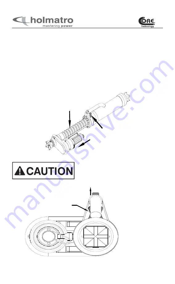
m e ch an ic al p lu ng er

loc k   p os ition

C a rry in g ha nd le

loc k 


6.1  Spreading


Extend the mechanical plunger. 


Hold the tool with one hand on the deadman’s handle, and the other hand on the 

carrying handle. 


Lift the deadman’s handle slightly to take the weight off the locking mechanism. 


Push the mechanical lock (A) to the left or the right to release the locking mechanism. 


Lift up the mechanical plunger (B) to the desired height. 


Release the mechanical lock. Make sure that the mechanical plunger is locked in one of 

the grooves. 


Once the ram is in position, operate the deadman’s handle to extend the hydraulic 

plunger. 

A

B

Mechanical plunger

with grooves


Make sure that the mechanical lock is in the locked 
position before operating the deadman’s handle. 
Operating the ram while the mechanical lock is 
unlocked can cause damage to the tool.   


Содержание CORE XR 4360 RAM

Страница 1: ...XR 4360 RAM Owner s Manual 918 269 303 001...

Страница 2: ...ll be provided upon written request of the technical department of your supplier If not provided contact Holmatro directly EXCEPT AS EXPRESSLY SET FORTH ON THE ENCLOSED WARRANTY CARD HOLMATRO MAKES NO...

Страница 3: ...Twin line version with a separate input pressure line and return line 2 A Core technology version with the input pressure line contained inside the return line Follow these instructions to ensure your...

Страница 4: ...shooting list In the event of unfamiliar noise vibration or other unusual behavior stop immediately and consult your dealer For Twin line tools never disconnect the quick action couplings when the pum...

Страница 5: ...Force NFPA 1936 HSF 22 385 lbs 99 6 kN Max spreading travel hydraulic 13 3 4 350 mm Max spreading travel mechanical 11 3 4 298 mm Full travel distance 30 1 2 775 mm including intermediate non moving P...

Страница 6: ...PERATION position If this happens first switch the pump pressure relief valve to the NEUTRAL position and then re connect the return hose of the tool CORE TOOLS The hydraulic system in the unit is pro...

Страница 7: ...ft or the right to release the locking mechanism Lift up the mechanical plunger B to the desired height Release the mechanical lock Make sure that the mechanical plunger is locked in one of the groove...

Страница 8: ...ked in one of the grooves Rotate the carrying handle The carrying handle can be rotated around the cylinder between two lock positions Never set the carrying handle in an unlocked position The mechani...

Страница 9: ...equipment if it is not in good condition Notify your dealer Check whether the guarantee registration card has been supplied and filled in Check whether the accessories are correctly mounted 7 2 Prepar...

Страница 10: ...from the female coupler if it has not released completely 4 Make sure you put the dust caps back onto the couplers when not in use This is an important step to keep dirt and foreign objects from getti...

Страница 11: ...car bodies see accessories section Use only original Holmatro accessories and attach them correctly 7 2 4 Shutting down On completion of the work retract the pistons back into the cylinders Check that...

Страница 12: ...devices and prevent kinking behind the attachment 2 Prevent kinking of the hoses and never bend the hoses beyond their minimum bending radius 89 mm 3 in 3 Do not pull the hoses to move tools or pumps...

Страница 13: ...but not pre connected to pressure or return hoseline Tool pressurized but not pre connected to hoseline Release pressure in tool using PRD Release pressure in tool using PRD Tool pressure relieved Pum...

Страница 14: ...turning valve stem all the way in clockwise Consult your Dealer Valve position in RELEASE Twin line or pump not pressurized Core 3 Check the coupling locking sleeve location Incorrect position Release...

Страница 15: ...sition of the pump pressure relief valve Core Check the pump valve block relief valve stem Valve in Neutral position Valve stem is all the way in Turn valve to OPERATION Turn valve stem all the way ou...

Страница 16: ...locking valve is activated Release the blocking valve a Turn control handle to CLOSE position momentarily b Turn handle to OPEN position The blocking valve should be released and the piston will exten...

Страница 17: ...having the unit checked at least once a year by a trained technician with the proper knowledge and the necessary tools Your dealer can carry out the annual maintenance on a contract basis on your beh...

Страница 18: ...fore lifting Qualified persons authorized by Holmatro may only make repairs and or service to Holmatro rescue tools An active and presently authorized Holmatro dealer may only disassemble the sealed p...

Страница 19: ...19 HOLMATRO DEALER TEL FAX TOOL MODEL NUMBER TOOL SERIAL NUMBER SERVICE RECORD DATE REPAIR SERVICE DESCRIPTION SERVICE TECHNICIAN Please make copies of this sheet as needed for future use...

Страница 20: ...20...

Отзывы: