WARNING! For proper operation, the voltage on the fuse holder wire should be 12-15 volts while the engine is running
and should remain above 8.5 volts while the engine is being started. Low voltage will result in poor
operation or an inoperative system. Double check the voltage after the installation is complete.
WARNING! The use of solid core ignition wires may adversely affect the function of the electronic control unit. We
recommend the use of suppression or spiral core wires.
NOTE:
Alternator output voltage is critical with the Pro-Jection system. If the alternator is not supplying specification output
(about 14 volts) when the engine is running, repair the system so it does supply the correct voltage.
13.0 FINAL CONNECTIONS
Plug the white 12-pin connector into the ECU. Install the harness bracket onto the ECU to hold the connector in place. To do
so, remove the two lower cover screws, install the bracket, and replace the screws.
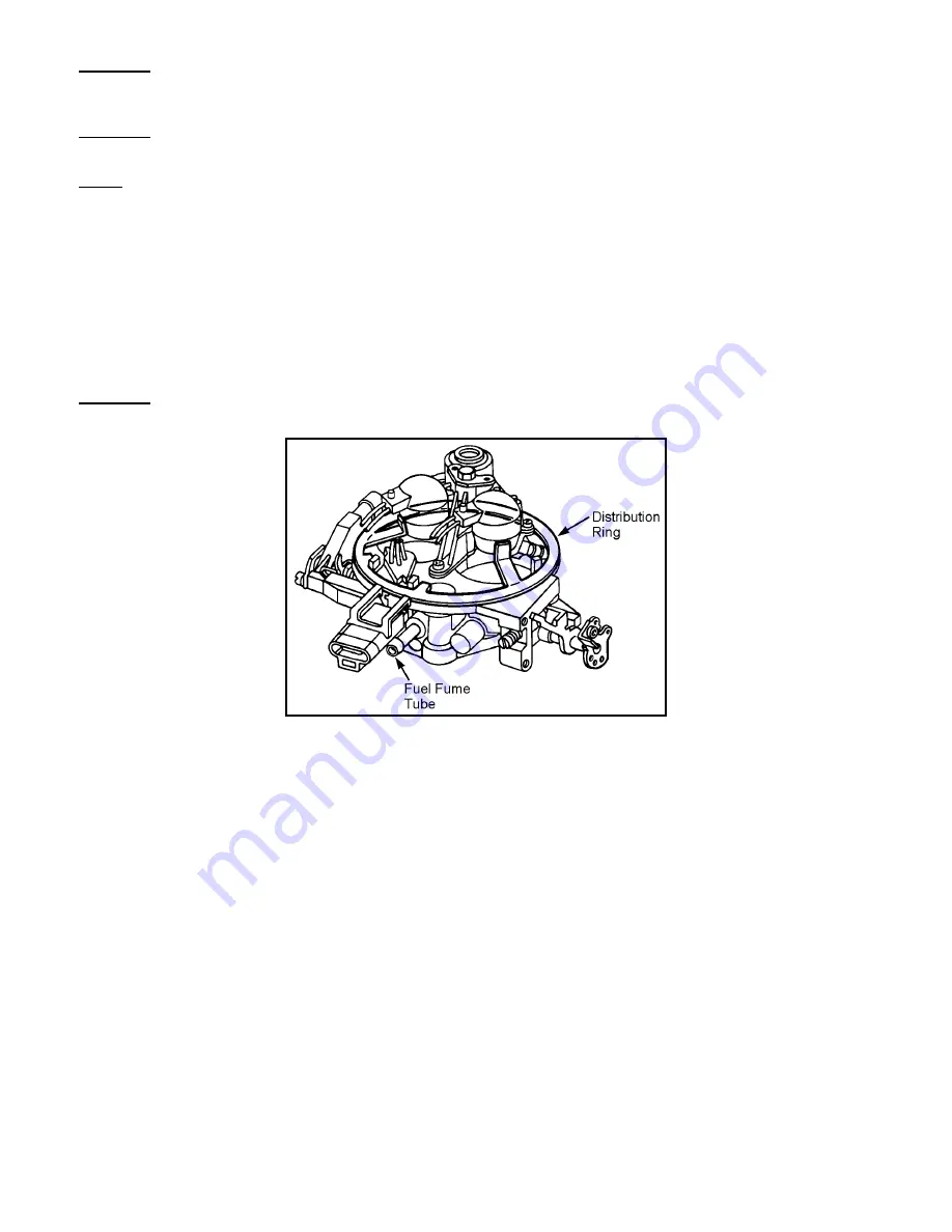
Shown in Figure 12 is the proper installation of the distribution ring on the throttle body. Be sure the tabs point upward and rest
along the injector pods. The injector pod screw closest to the TPS switch must be removed and reinstalled to hold the
distribution ring in place.
WARNING! It is important for the distribution ring to be properly installed and retained. Failure to do so will cause
inadequate seal between the throttle body and flame arrestor and may be a fire hazard in the event of a
backfire.
Figure 12
14.0 OPERATIONAL OVERVIEW OF THE DIGITAL ECU
This digital ECU is programmed at the factory with fuel maps. The ECU utilizes inputs from various sensors and from the
adjustment knobs located on the front of the ECU to calculate the appropriate fuel delivery to the engine.
When the ignition switch is in the "On" position, battery power is applied to the red wire of the ECU, fuel pump (+) terminal and
one side of each injector coil. Upon initial power up, the fuel pump will run for a couple of seconds to help prime the fuel lines.
The ECU controls the pump by grounding the green wire going to the (-) terminal of the pump. As the engine is being started,
battery power is applied to the pink wire, which enables the ECU to operate the fuel pump, and pulses the injectors, so fuel is
delivered into the throttle body. After the engine starts up and the ignition switch is released from the crank position, the ECU
relies on tach signals from the white wire to operate the pump and injectors to run the engine. If for some reason the engine
stalls, this is most likely due to the absence of tach signals, which causes the ECU to shut off the injectors and the fuel pump.
The temperature sensor is designed to have a high resistance when cold (about 10K ohms at 20
°
F) and a low resistance when
warm (about 200 ohms at 200
°
F). This sensor tells the ECU to deliver a richer fuel mixture during cold engine operation and
gradually leans out at the engine warms up. The brown wire can be grounded to disable the choke function. This may be
required if the coolant temperature is less than 150 when the engine is fully warmed up.
The throttle position sensor (TPS) tells the ECU how far and how fast the throttle is opened. The ECU sends a 5 volt reference
signal to the TPS along the gray wire and the voltage on the blue wire varies depending on how far the throttle is opened. A low
voltage appears at idle with the voltage increasing as the throttle is moved to open. A “CLEAR FLOOD” mode has also been
programmed into the ECU to aid in vehicle startup in case excessive fuel has entered the intake manifold. Should the engine
flood during start up, the clear flood mode can be initialized by turning the ignition off, opening the throttles fully and cranking the
engine until it starts. There is also a back-up mode, which allows the boat to be driven in the event of TPS failure. If the TPS


