background image

HOKUYO AUTOMATIC CO.,LTD. 


ENFORCEMENT 

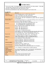
* Clean up lens surface of both light-projecting and receiving part with soft cloth periodically.  When light- 

projecting and receiving part are dirty, it can't keep specific detection area. 

* Don't make a wiring with power line such as driven motor or break. 
* Earth frame ground terminal to the body when switching regulator is used as power source. 


2. Specifications 

Model No. 

PBS-03JN 

Power source 

24VDC(Operating range 18 to 30VDC, ripple within 10%) 

Current consumption 

250mA or less(100mA or less when emission stops) 
(Note) Except for I/O terminal current and rush current(500mA) 

Detectable object and 
detecting distance 

White kent paper with 300

×

300mm(Placed in parallel with sensor projecting/

receiving surface) 
Area with vertical direction 0.2 to 3m and width 2m(Origin point is scanning center 
position) but within scanning angle 180 degrees 

Hysteresis 

It specifies the width when each area setting(Original value : 10%) 
    10% of detecting distance(It is not getting 60mm or less) 
    5% of detecting distance(It is not getting 30mm or less) 

Output(Note) 
 

Photo-coupler/open-collector output(30VDC 50mA Max.) 
Output 1 : OFF when detected in area 
Output 2 : OFF when detected in area 
Output 3 : OFF when detected in area 
Trouble output : ON during normal operation 
(Note) Output 1 to 3 show the state it is detecting object when this output executes 

Response time 

Normal operating mode : 180ms or less(Scanning time 100ms/1 rev.) 
Low-speed scanning mode : 200ms or less(Scanning time 110ms/1 rev.) 
2-scanning operating mode : the above time + each scanning time 
Note) When area changeover, further 1 scanning time is delayed. 

Starting time 

Within 1s after putting power source on or stopping LED emission 

Lamps 

Power lamp(Green) : Flickers when troubled 
Output 1 lamp(Orange) : Lights up when detected in area 
Output 2 lamp(Orange) : Lights up when detected in area 
Output 3 lamp(Orange) : Lights up when detected in area 

Connection method 

Lead wire 1m long 

Ambient illuminance 

Halogen/mercury lamp : 10000lux or less 
Fluorescent lamp : 6000lux(Max. illuminance) 
Note) It may malfunction when receiving strong light such as sun light etc. 

Ambient temperature/ 
humidity 

-10 to +50 degrees C, 85%RH or less(Not condensing and icing) 

Vibration resistance 

10 to 55Hz, double amplitude 1.5mm    Each 2 hour in X, Y and Z directions 

Impact resistance 

490m/s

2

(50G)    Each 10 time in X, Y and Z directions 

Protective structure 

IP64 

Weight 500g 
Life 

5 years during normal temperature(motor life) 

Material 

Front case : Polycarbonate, rear case : ABS 


Title 

Measuring Distance Type Obstacle Detection 

Sensor PBS-03JN Series  Instruction Manual 

Drawing 

No.


C-41-2342 7/19 

Содержание PBS-03JN

Страница 1: ...read this instruction manual and keep properly Symbol Amended reason Pages Date Corrector Amended No Approved by Checked by Drawn by Designed by Title Measuring DistanceType Obstacle Detection Sensor...

Страница 2: ...branch office with the following information The contents of relative name plate or specifications model name production No type production date etc Abnormal condition more in detail including condit...

Страница 3: ...to handle the device and don t hit against or drop off This device can t detect a dead space of view in beam scanning angle If necessary detecting area isn t enough don t use it 5 6 6 6 6 13 The follo...

Страница 4: ...vel and instruction stated here are all important matter ENFORCEMENT Pages Clean up lens surface of both light projecting and receiving part with soft cloth periodically When light projecting and rece...

Страница 5: ...ure Light scanning image DANGER This product is auxiliary safety device and isn t complete safety device When device is used for application that may occur serious accident make sure to prepare other...

Страница 6: ...install at the places where strong light over rated enters into reception part It may cause mis operation PROHIBITION Don t decompose this device It may cause any troubles by short circuit Moreover i...

Страница 7: ...when detected in area Trouble output ON during normal operation Note Output 1 to 3 show the state it is detecting object when this output executes Response time Normal operating mode 180ms or less Sca...

Страница 8: ...udges with 1 scanning under normal operating Mirror reflecting avoidance mode It sets when each detecting area setting It hardly detects the objects with high reflectance 20m away but min detecting wi...

Страница 9: ...outer input response time is getting slower Changeover time with approx 100 to 110msec is added to response time 3 4 Trouble output When revolution of scanner Motor stopped or it didn t receive LED s...

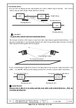
Страница 10: ...plate about 20 meter along it may malfunction because of multi reflection Mirror reflecting avoidance mode reduces frequency of malfunction If detecting object is too small it can t detect under this...

Страница 11: ...Connect unused output cable to output common Gray or open it 4 2 Operating lamp 5 Detecting area setting 5 1 Detecting area setting software Start application software and set detection area with mou...

Страница 12: ...a width of short distance and long distance as follows D1 mm W 100 30 D2 mm D1 L tan 0 9 degrees tan 0 9 degrees 0 016 5 4 Detection guarantee range and detection area diagram Title Measuring Distance...

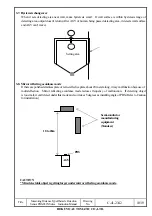
Страница 13: ...zone and it can t detect Setting origin point of detecting distance is the center position of scanning 6 Caution for installation 6 1 Relation with cover Install PBS so that it sticks 50mm or more awa...

Страница 14: ...s against mechanical axis is follows Dispersion between optical axis and mechanical axis ENFORCEMENT Install firmly not to dislocate optical axis by vibration or impact Make a optical axis adjustment...

Страница 15: ...on against other receiving light In case of undermentioned applications don t use 2 scanning mode because response is delayed and AGV s may collide Use other PBS with low speed scanning mode due to be...

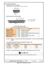
Страница 16: ...ck to be ready CD Carrier Detect Input Detection of carrier CAUTION Make sure to short circuit about unused pin among RTS CTS and CD and between DTR and DSR c Colors and functions of PBS s cable and w...

Страница 17: ...ecause it judges with 1 8 degrees 1 scanning respectively See item 8 about mutual nterference Q Do you have any countermeasures to prevent interference A Take a installation angle to PBS and see about...

Страница 18: ...we can t guarantee to use at the places under any drop of water Q When PBS suddenly receives a strong vibration during operating how does it operate A It will not affect if it is within 70Hz is less...

Страница 19: ...ieki Nakamura Ku Nagoya 450 0002 Japan Tel 052 582 4641 Fax 052 551 6906 Osaka Office 1 10 9 Niitaka Yodogawa Ku Osaka 532 0033 Japan Tel 06 6394 2102 Fax 06 6394 2339 Kyushu Office KMM Bldg 2 11 15As...

Отзывы: