HOKUYO AUTOMATIC CO.,LTD.
5-2. Origin of detecting area setting
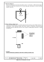
Origin point(X=0, Y=0) of detecting area setting is the center position of beam scanning.
5-3. Setting not for detecting the wall
Set detection area 100mm or more away from the wall. After checking operating state with detection area
setting software, adjust and change detecting area. PB9 is scanned by driving the mirror with pulse motor.
Make a far area setting as follows by considering step error because step error of pulse motor is +/- 0.9
degrees.
When width of passageway is 2W and max. detecting distance is L, calculate the area width of short distance
and long distance as follows:-
D1(mm) = W – 100 -30
D2(mm) = D1 – L*tan(0.9 degrees) tan(0.9 degrees) = 0.016
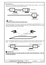
5-4. Detection guarantee range and detection area diagram
Title
Measuring Distance Type Obstacle Detection
Sensor PBS-03JN Series Instruction Manual
Drawing
No.
C-41-2342 12/19
Center of beam scanning
X, Y = 0
Y
X
AGV
W
L
D1
D2
Wall, device
Wall, device
PBS
2m
3m
Scanning setting available range
Detection guarantee range
White kent paper with 300
×
300mm(Placed in
parallel with sensor projection/reception
surface)
Area with vertical direction 0.2 to 3m and width
2m but within scanning angle 180 degrees
(Width of detectable object is getting larger
under mirror reflecting avoidance mode.)
Setting value of detection area should be set
within 180 degrees as detection range.


