background image

7

 Adres producenta/ Adresse des Herstellers/ Manufacturer’s Address/ Адрес производителя 

GTV Poland Sp. z o.o. Sp. k., ul. Przejazdowa 21, 05-800 Pruszków

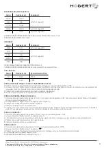
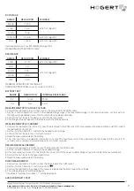
DC VOLTAGE

RANGE

RESOLUTION

ACCURACY

200 uA

100 nA

±(1.8% of rdg +2D)

2 mA

1 uA

20 mA

10 uA

200 mA

100 uA

±(2.0% of rdg +2D)

10 A

10 mA

±(2.0% of rdg +10D)


Overload protection: Fuse 500mA/250V (range 10A)

MEASURING VOLTAGE DROP: 200mV

RESISTANCE

RANGE

RESOLUTION

ACCURACY

200 Ω

0.1 Ω

±(1.0% of rdg +10D)

2 KΩ

1 Ω

±(1.0% of rdg +4D)

20 KΩ

10 Ω

200 KΩ

100 Ω

2 MΩ

1 KΩ


MAXIMUM OPEN CIRCUIT VOLTAGE: 3 V

OVERLOAD PROTECTION: max 15 seconds 220 V rms.

BATTERY TEST

   RANGE

RESOLUTION

INTERNAL RESISTANCE

9 V

10 mV

900 Ω

1.5 V

1 mV

3 KΩ

MEASUREMENT OF DC AND AC VOLTAGE

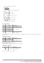
 1.  Connect the red lead to the „V Ω mA” socket, the black lead to the COM socket.

2.  Set the „Function Selection” switch to the needed voltage range if the measured voltage is not known in advance, set the switch to 

the highest range and decrease it until a satisfactory reading is obtained.

3. Connect the test leads to the device or circuit to be measured.

4. The voltage value will appear on the display with the voltage polarity.

MEASUREMENT OF DC CURRENT 

1.  Connect the red lead to the „V Ω mA” socket. The black lead to the COM socket (for measurements between 200mA and 10A, connect 

the red lead to 10A socket)

2. Set the „Function Selection” switch to the needed current range.

3. Connect the test leads to the circuit with current.

4. Read the measured value on the display.

5.  The „10A” function is intended for intermittent use only. The maximum contact time between the test leads and the circuit is 15 

seconds, with a minimum interval between tests of a few seconds.

RESISTANCE MEASUREMENT

1. Connect the red lead to „V Ω mA” socket. The black lead to the COM socket.

2. Set the „Function Selection” switch to the needed Ω range. 

3. If the measured resistance is connected to the circuit, turn off the power and discharge all capacitors before the measurement.

4. Connect the test leads to the measured circuit.

5. Read the measured value on the display.

DIODE MEASUREMENT

1. Connect the red lead to „V Ω mA” socket, the black lead to the COM socket.

2. Set the „Function Selection” switch to position”

” 

3. Connect the red lead to the anode of the measured diode and the black lead to the cathode.

4. The voltage drop in mV will be displayed. 

If the diode is inverted, the number „1” will be displayed.

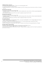
AUDIO CONTINUITY TEST

Содержание HT1E602

Страница 1: ...Przy napi ciu przekraczaj cym 60 V dla pr du przemiennego i 30 V dla pr du sta ego nale y zachowa szczeg ln ostro no przed niebezpiecze stwo pora enia pr dem U yj odpowiednich zacisk w funkcji i zakre...

Страница 2: ...i 600 V pr du sta ego lub 600 V warto ci skutecznej dla wszystkich zakres w NAPI CIE PR DU PRZEMIENNEGO AC Zakres Rozdzielczo Dok adno 200 V 100 mV 2 0 of rdg 10D 600 V 1 V redni wynik skalibrowany w...

Страница 3: ...jawi si na wy wietlaczu z polaryzacj napi cia POMIAR NAT ENIA PR DU STA EGO DC 1 Czerwony przew d pod acz do gniazda V mA Czarny przew d do gniazda COM dla pomiar w mi dzy 200mA a 10A pod cz czerwony...

Страница 4: ...rjesttypuPNPlubtypuNPN izlokalizujprzewodyemitera bazyikolektora W przewodydoodpowiednich otwor w gniazda hFE 3 Miernik wy wietli przybli on warto hFE w warunkach pr du podstawowego 10 A i V CE 2 8V T...

Страница 5: ...ange the range during measurement When voltages exceed 60 V for AC and 30 V for DC special care must be taken against the danger of electric shock Use the appropriate terminals functions and range for...

Страница 6: ...20 V rms for 200 mV and 600 V DC or 600 V rms for all ranges AC VOLTAGE RANGE RESOLUTION ACCURACY 200 V 100 mV 2 0 of rdg 10D 600 V 1 V Average score calibrated in rms sinusoidal wave FREQUENCY RANGE...

Страница 7: ...ltage polarity MEASUREMENT OF DC CURRENT 1 Connecttheredleadtothe V mA socket TheblackleadtotheCOMsocket formeasurementsbetween200mAand10A connect the red lead to 10A socket 2 Set the Function Selecti...

Страница 8: ...e value of hFE under 10 A and CE 2 8V base current conditions BATTERY TESTING 1 Connect the black lead to the COM socket and the red lead to the V mA socket Note The polarity of the red lead is positi...

Страница 9: ...60 V f r Wechselstrom und 30 V f r Gleichstrom ist besondere Vorsicht zu bewahren im Hinblick auf die Gefahr eines Stromschlags Verwenden Sie die entsprechenden Klemmen Funktionen und den richtigen B...

Страница 10: ...reich 200 mV und 600 V Gleichstrom oder 600 V Effektivwert f r alle Bereiche AC WECHSELSPANNUNG Bereich Aufl sung Genauigkeit 200 V 100 mV 2 0 of rdg 10D 600 V 1 V Mittleres Ergebnis kalibriert in rms...

Страница 11: ...ie die Messkabel an das gemessene Ger t oder den gemessenen Stromkreis an 4 Der Spannungswert erscheint f r einen Moment auf der Anzeige mit der Polung der Spannung MESSUNG DER GLEICHSTROMST RKE DC 1...

Страница 12: ...vom Typ PNP oder vom Typ NPN ist und lokalisieren Sie die Leitungen von Emitter Basis und Kollektor Legen Sie die Kabel in die entsprechenden ffnungen der hFE Buchse 3 Das Messger t zeigt den ungef h...

Страница 13: ...roducenta Adresse des Herstellers Manufacturer s Address GTV Poland Sp z o o Sp k ul Przejazdowa 21 05 800 Pruszk w RU HT1E602 60 30 hFE 3 1999 0 6 45 x 23 2 1 0 C 40 C 80 10 C 50 C 85 2 AAA 4 160 x 7...

Страница 14: ...s Herstellers Manufacturer s Address GTV Poland Sp z o o Sp k ul Przejazdowa 21 05 800 Pruszk w DC 200 100 0 5 3 2 1 0 8 5 20 10 200 100 600 1 1 0 5 200 220 600 AC 200 100 2 0 10 600 1 45 450 1000 750...

Страница 15: ...ul Przejazdowa 21 05 800 Pruszk w 200 100 A 1 8 2 2 A 1 A 20 A 10 A 200 A 100 A 2 0 2 10A 10 A 2 0 10 500 250 10 200 200 0 1 1 0 10 2 K 1 1 0 4 20 K 10 200 K 100 2 M 1 K 3 15 220 9 V 10 mV 900 1 5V 1...

Страница 16: ...tellers Manufacturer s Address GTV Poland Sp z o o Sp k ul Przejazdowa 21 05 800 Pruszk w 3 4 1 1 V mA COM 2 3 30 20 HFE 1 hFE 2 PNP NPN hFE 3 hFE 10 VCE 2 8 1 COM V mA 2 1 5 9 12 BATT 3 4 500 A 250 V...

Отзывы: