[47]
□
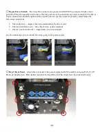
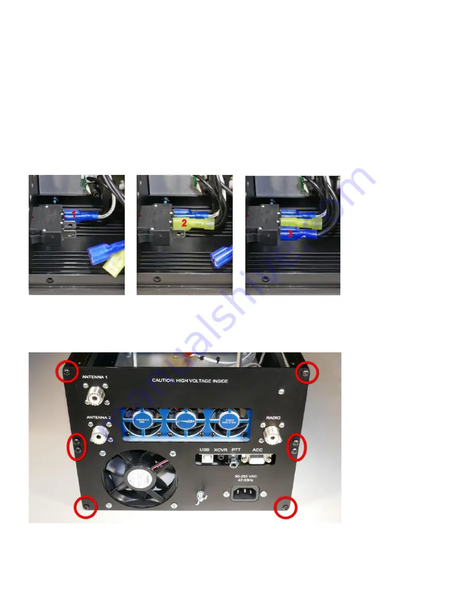
Step 6: Power Switch
– The wires that connect to the power switch MUST be connected in the correct
positions. Place the amplifier on its side so that the power switch connections are easily accessible. The QC or
Faston connections should be tight and may require pliers to get the connecter properly seated. Make the
following connections:
1.
The neutral wire – single white wire (terminal may be blue or red)
2.
The line distribution wire – three black wires, yellow terminal
3.
The AC line from the inlet – single black wire, blue terminal
Use the remaining zip tie to bundle the wires going to the power switch.
□
Step 7: Rear Panel
– Attach the rear panel to the power supply and LPF assembly using eight #6-32 3/8”
black, pan head screws. Only tighten rear panel screws after all of the screws have been inserted loosely.

