background image


[38] 


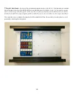
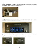
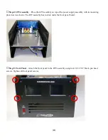
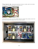
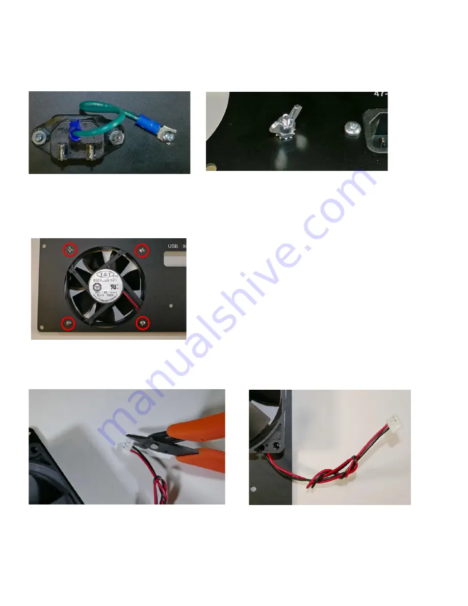
Step 9: Ground Stud – 

Use a #6-32 X ½” screw, #6-32 hex nut with integral lock washer and the and #6-32 

wing nut to secure one end of the green ground wire to the reap panel. Attach to other end of the green ground 
wire to the ground terminal of the power inlet. 


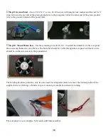
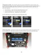
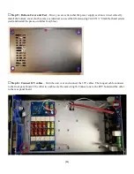
Step 10: Mount 80mm Fan – 

Use the remaining four #4-40 X ½” to attach the 80mm fan to the rear panel, 

the screws tap themselves into the fan. The fan label should be visible through the rear panel and the fan wire 
should be on the side closest to the ground stud. 


The fan plug has three positions, only two are used. Use diagonal cutters to remove the unused position. The 
supplied wire is a bit long so bundle it up so it cannot get into the fan when it is turning. 


The rear panel is now complete. Set it aside until final assembly. 

Содержание HARDROCK-50

Страница 1: ...Hardrock 500 Assembly Instructions Run 1 2020 Jim Veatch WA2EUJ 30 August 2020 500 Assembly Instructions 500 Assembly Instructions ...

Страница 2: ... ASSEMBLY INVENTORY 7 7 FRONT PANEL ASSEMBLY INVENTORY 9 8 CHASSIS PACK INVENTORY 10 9 LARGE ITEM INVENTORY 12 10 LPF ASSEMBLY 14 BUILD OPTIONS 15 ASSEMBLY INSTRUCTIONS 15 11 POWER SUPPLY ASSEMBLY 25 ASSEMBLY INSTRUCTIONS 26 12 REAR PANEL ASSEMBLY 34 ASSEMBLY INSTRUCTIONS 35 13 FRONT PANEL ASSEMBLY 39 ASSEMBLY INSTRUCTIONS 39 14 FINAL ASSEMBLY 44 15 SETTING THE BIAS 61 PREREQUISITES 61 APPENDIX A ...

Страница 3: ...250 watts DC Output 13 5V 2A max for powering transceiver Cooling RF deck 3 fans 32CFM Power Supply 1 Fan 26 CFM In Out Jacks Three UHF connectors 1 radio 2 antenna Size 9 W by 7 H by 14 2 D 229mm W by 178mm by 361mm not including switches and connectors Weight 16 5 lbs 7 2 Kg under 18 lbs 8 2 Kg with ATU Metering VDD 0 60 Volts IDD 0 20 Amperes Forward Power 0 500 Watts Reflected Power 0 50 Watts...

Страница 4: ...ing a potentially dangerous conditions Never operate the Hardrock 500 if there is the potential for water in or near the environment surrounding the Hardrock 500 If liquids are present or inadvertently enter the Hardrock 500 s enclosure immediately remove the AC power by disconnecting it at the source and do not operate the Hardrock 500 until completely dry conditions can be assured High Level RF ...

Страница 5: ...t areas Wire Stripper For making the coax jumpers Long nose pliers For general mechanical assembly Nutdriver Not essential but helps with panel assembly If only metric tools are available use pliers or an adjustable wrench Toothpick For unbraiding coax Adjustment tool or small flat blade screwdriver Turning pots Thread locker Loc Tite 242 or similar to prevent screws from loosening optional Digita...

Страница 6: ... M F THREADED SPACER 4 40X1 4 PAN HEAD SCREW 4 40 HEX NUT WITH LOCK WASHER 4 40X1 4 FLAT HEAD SCREW T80 6 CORE YELLOW T80 2 CORE RED 20 ENAMELED WIRE 28 ENAMELED WIRE 18 TEFLON WIRE color may vary FT82 43 GRAY 4 PASS ASSEMBLY INVENTORY PICTURE QUANTITY 15 QUANTITY 4 4 4 4 4 6 4 8 15 5 6 2 ...

Страница 7: ... WASHER 4 40X1 4 PAN HEAD SCREW 4 40 3 6 JACK SCREW W NUT WSR 4 40X1 4 FLAT HEAD SCREW CAP ALUM 10000UF 20 80V SNAP CAP ALUM 1000UF 20 63V JST 3 PIN SHELL CABLE TIES COLOR MAY VARY AC NEUTRAL CABLE 5 POWER SUPPLY ASSEMBLY INVENTORY PICTURE QUANTITY 16 16 16 2 MAYBE INSTALLED IN ACC JACK 6 1 1 3 5 1 ...

Страница 8: ...AC LINE CABLE AC SWITCH WIRE 14 WIRE 19 14 RED BLACK ZIP WIRE WITH SPADE TERMINALS 4 6 9 14 RED BLACK ZIP WIRE 6 6 1 1 3 1 ...

Страница 9: ...THREADED ALUMIN SPACER 4 40 HEX NUT WITH LOCK WASHER 6 32 HEX NUT NYLON BLACK 6 32 1 NYLON SCREW BLACK 6 32X1 2 PAN HEAD SCREW GROUND LUG AC INLET 6 32 HEX NUT WITH LOCK WASHER 6 32 WING NUT 4 40 1 2 STEEL PAN HEAD SCREW FAN MOUNTING Ground Wire 7 REAR PANEL ASSEMBLY INVENTORY PICTURE QUANTITY 12 13 1 1 12 12 3 3 1 4 1 ...

Страница 10: ... 8 POWER ENTRY MODULE AC INLET 1 80MM X 25MM 12VDC FAN W 2 PIN CONN 1 CONN UHF CHASSIS MOUNT 3 FAN AXIAL 40X20MM 12VDC 3 ...

Страница 11: ...ACK OXIDE 4 40 HEX NUT WITH LOCK WASHER CONN HEADER VERT 36POS 2 54MM CONN HEADER VERT 40POS 2 54MM ARDUINO STACKING HEADERS 6 PIN AND 8 PIN 2 EA LCD DISPLAY 2 8 TOUCHSCREEN ARDUINO MEGA 2560 CIRCUIT BREAKER WITH SWITCH 20A RED ILLUM 9 FRONT PANEL ASSEMBLY INVENTORY PICTURE QUANTITY QUANTITY 4 4 4 1 2 2 2 1 1 ...

Страница 12: ...ACK 4 40 X 0 75 Threaded Rod 4 NYLON WASHER 4 40 HEX NUT WITH LOCK WASHER 4 40 1 2 STEEL PAN HEAD SCREW MOSFET MOUNTING 6 32X1 2 PAN HEAD SCREW RUBBER FEET RIBBON CABLE 8CM 3 2X5 PIN 0 1 RIBBON CABLE 35CM 13 8 2X5 PIN 0 1 10 CHASSIS PACK INVENTORY PICTURE QUANTITY QUANTITY 16 12 4 8 4 4 4 4 1 2 ...

Страница 13: ... 11 12V Power Cables 2 PIN Polarized 35CM 13 8 2 12V Power Cables 2 PIN Polarized 50CM 19 7 1 AMP CONTROL CABLE 4 PIN Polarized 25CM 1 RG 316 COAX CABLE 18 RG 58 COAX CABLE 24 THERMAL COMPOUND PACKET 2 ...

Страница 14: ...9 LARGE ITEM INVENTORY DESCRIPTION MEANWELL EPP 400 18 18V 22A DC Supply SIDE PANELS FRONT PANEL REAR PANEL TOP BOTTOM PANEL PANEL RF DECK 12 EM INVENTORY PICTURE QUANTITY 3 4 1 1 2 1 ...

Страница 15: ...PANEL POWER SUPPLY HEATSINK COPPER HEAT SPREADER 200mm X 200mm THERMAL PAD PCB Set Power PCB LPF PCB Rear Panel PCB and Front Panel PCB 13 1 1 1 1 4 ...

Страница 16: ...pplied without the toroidal inductors installed These must be wound and installed on the LPF board Here are photos of the LPF board as supplied in the kit Notice that several of the components are not installed Check the photos against the PCB supplied with your kit for verification LPF PCB Top Side LPF PCB Bottom Side ...

Страница 17: ...y Tips for Winding Toroidal Inductors 1 The enamel on wire included with the kit is designed to be removed by scraping After the inductor is wound scrape off as much of the enamel as possible tin the end with a soldering iron which will remove the remaining enamel and prepare the inductor for installation on the PCB Repeat this process until the inductor lead is thoroughly coated with solder 2 The...

Страница 18: ... correctly Step 2 L10A 7 turns 8 in 20 3cm of 20 enameled wire on a T80 6 yellow toroid core Wind the inductor scrape and tin the leads then insert to inductor into the PCB at the marked location solder and trim excess leads Step 3 L10B 5 turns 7 in 17 8cm of 20 enameled wire on a T80 6 yellow toroid core Wind the inductor scrape and tin the leads then insert to inductor into the PCB at the marked...

Страница 19: ...tin the leads then insert to inductor into the PCB at the marked location solder and trim excess leads Step 5 L17B 8 turns 10 in 25 4cm of 20 enameled wire on a T80 6 yellow toroid core Wind the inductor scrape and tin the leads then insert to inductor into the PCB at the marked location solder and trim excess leads ...

Страница 20: ... tin the leads then insert to inductor into the PCB at the marked location solder and trim excess leads Step 7 L30B 9 turns 10 in 25 4cm of 20 enameled wire on a T80 2 red toroid core Wind the inductor scrape and tin the leads then insert to inductor into the PCB at the marked location solder and trim excess leads ...

Страница 21: ... to inductor into the PCB at the marked location solder and trim excess leads Two of these coils are required L60A and L80B as shown Step 9 L60B 15 turns 16 in 40 6cm of 20 enameled wire on a T80 2 red toroid core Wind the inductor scrape and tin the leads then insert to inductor into the PCB at the marked location solder and trim excess leads ...

Страница 22: ...tin the leads then insert to inductor into the PCB at the marked location solder and trim excess leads Step 11 L16A 20 turns 20 in 50 8cm of 20 enameled wire on a T80 2 red toroid core Wind the inductor scrape and tin the leads then insert to inductor into the PCB at the marked location solder and trim excess leads ...

Страница 23: ...304 30 turns 30 in 76 2cm of 28 enameled wire on a T82 43 gray toroid core Wind the inductor scrape and tin the leads then insert to inductor into the PCB at the marked location solder and trim excess leads Two of these coils are required T303 and T304 as shown T303 and T304 each have four holes in the PCB for wires Be sure to insert the 28 wire in the holes with the smaller diameter The larger ho...

Страница 24: ...s and bend the wires into a U shape Save the excess wire for the rear panel board Step 15 T303 T304 insert the 18 wire U created in step 14 through T303 and T304 into the larger diameter holes on either side of the cores Solder the U wires in place and trim excess leads Note JP2 is shown installed for normal operation ...

Страница 25: ...ar cutout in towards the bottom as shown At the four locations indicated in blue insert a 6 he panel into a 6 32X1 75 F F threaded stand off Tighten At the four locations indicated in red insert a 4 40X1 4 4 40 1 4 M F threaded aluminum spacer Tighten securely use thread Place the LPB board on the 4 40 spacers installed in the last step T303 and If you have purchased the ATU use the 4 40 1 F F thr...

Страница 26: ... 1 of the amp the counter sink is on the wrong side of the panel In this case there is plenty of clearance for the flat head screws and we decided to assemble the amps using the panels as built The screws are not visible once the amp is assembled The assembly is now complete the amp deck will be added later Place the assembly in a safe place to avoid potentially scratching the side panels ...

Страница 27: ...ction covers the steps requires to construct the Power Supply Assembly The Power PCB is supplied without the large electrolytic installed These must be installed on the Power board Here are photos of the Power board as supplied in the kit ...

Страница 28: ...d be bad please observe the capacitor polarity when inserting the capacitors into the PCB and recheck that they are correct before soldering Assembly Instructions Step 1 C201 Insert C201 the 10000 uF 80V capacitor into the power board with the negative side of the cap closest to the edge of the PCB DO NOT SOLDER AT THIS TIME Step 2 C206 Insert C206 the 1000 uF 63V capacitor into the power board wi...

Страница 29: ...B one more time to make 100 certain that C201 and C206 are oriented correctly Solder them to the PCB and trim any excess leads Locate the Power Supply Panel and orient it so that the large cutout is to the left and the side with three rectangular cutout in towards the bottom as shown At the sixteen locations indicated in blue insert a 4 40X1 4 4 40 1 4 M F threaded aluminum spacer Tighten securely...

Страница 30: ...egral lock washer 12 locations Step 7 Power PCB Supplies Place the power PCB in the lower right position on the power supply plate the DC terminals go to the left and the USB and DB9 connectors go to the right Secure using 4 40 nuts with integral lock washer 4 locations For steps 8 12 please view the video I created that shows how to install the AC wiring You can view the video at https sites goog...

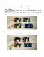
Страница 31: ...crimp connector The common end has a yellow crimp terminal place this terminal at the right edge of the power supply plate 1 Put the JST pin on the shortest wire in CN1 Pin 1 AC Neutral of the power supply in the upper right of the power supply plate 2 Put the JST pin on the middle length wire in CN1 Pin 1 AC Neutral of the power supply in the upper left of the power supply plate 3 Put the JST pin...

Страница 32: ...ft of the power supply plate 2 Put the JST pin on the middle length wire in CN1 Pin 3 AC Line of the power supply in the upper left of the power supply plate 3 Put the JST pin on the longest wire in CN1 Pin 3 AC Line of the power supply in the upper right of the power supply plate Step 11 AC Switch Wire The AC Switch wire is a single conductor with blue crimp terminals on either end Place it with ...

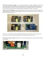
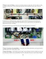
Страница 33: ... Be certain that these washers are on top of the terminals not underneath and aligned with the terminal not diagonal The negative terminal is closest to the power LED and the voltage adjustment pot as shown here Step 13 Power Board Terminal Blocks Loosen the screws in the terminal blocks on the power board by turning the screws CCW units you hear a click Step 14 DC Wiring Locate the three power su...

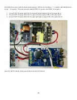
Страница 34: ... positive and NEG for negative 1 Connect the 4 DC power cable from the lower left power supply to PS3 on the power board 2 Connect the 6 DC power cable from the upper left power supply to PS2 on the power board 3 Connect the 9 DC power cable from the upper right power supply to PS1 on the power board Leave the AMP terminals on the power board unconnected at this time ...

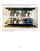
Страница 35: ...d use 6 4 40 X flat head screws to attach the side panels to the top of the Power supply panel use thread locker if available The assembly is now complete the amp deck will be added later Place the assembly in a safe place to avoid potentially scratching the side panels ...

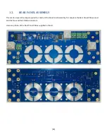
Страница 36: ...SSEMBLY This section covers the steps required to construct the Rear Panel Assembly To complete the Rear Panel PCB we must add the fans and the SO239 connectors Here are photos of the Rear Panel PCB as supplied in the kit ...

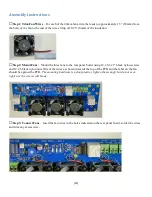
Страница 37: ...ee fans to the rear panel board using 12 6 32 1 black nylon screws and 12 6 black nylon nuts Orient the wires as shown towards the top of the PCB and the label on the fan should be against the PCB The mounting hardware is nylon plastic tighten them snugly but do not over tighten or the screws will break Step 3 Connect Fans Insert the fan wires in the holes indicated on the rear panel board solder ...

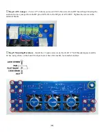
Страница 38: ...e ends and create a jumper from the RF pin of ATU IN to the RF pin of ATU OUT Tighten the screws in the terminal blocks Step 5 Mounting Hardware Install the 12 jack screws red the 4 40 M F threaded spacer and the 4 hex nut yellow on the board Each jack screw has a flat washer lock washer and nut ...

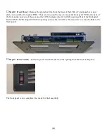
Страница 39: ...he SO239 jacks Step 7 SO239 screws Use the thirteen 4 40 X screws to fasten the SO239 jacks and the spacer to the rear panel Then solder the center pins of the SO239 jacks Step 8 Power Inlet Use two 6 32 X screws and 6 32 hex nuts with integral lock washers to attach the power inlet to the rear panel Please orient the inlet as shown with the ground tab up ...

Страница 40: ... remaining four 4 40 X to attach the 80mm fan to the rear panel the screws tap themselves into the fan The fan label should be visible through the rear panel and the fan wire should be on the side closest to the ground stud The fan plug has three positions only two are used Use diagonal cutters to remove the unused position The supplied wire is a bit long so bundle it up so it cannot get into the ...

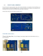
Страница 41: ...e Arduino Mega processor All of these components are socketed for easy replacement Pay careful attention to which side of the PCB the LCDs and the Arduino are mounted Here are photos of the Front Panel board as supplied in the kit Assembly Instructions Step 1 LCD Jumper Wires The LCD displays need jumpers added to SB1 SB2 and SB3 Do this on both LCD displays BEFORE AFTER ...

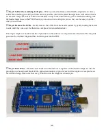
Страница 42: ...he PCB edges Step 2 Stacking Headers Carefully slide the Arduino stacking headers onto the pins of the LCDs There are 6 pin and 8 pin headers make sure that the placement is correct Step 3 Mount LCDs On the side of the front panel PCB that says INSTALL LCD DISPLAYS ON THIS SIDE insert the LCDs with the stacking headers attached It s a bit of a challenge to get all of the pins lined up Step 4 Solde...

Страница 43: ...ut them Step 6 Remove the LCDs Gently remove the LCDs from the header sockets by gently rocking them side to side until they come out Set them in a safe place for reinstallation later The 40 pin single row headers and the 35 pin dual row headers have a long side and a short side The long side goes into the Arduino Mega and the short side goes into the PCB Step 7 Insert Pins Insert the dual header ...

Страница 44: ... of solder to accumulate on top of the board There is no need to trim and of the pins on the Mega Step 10 Reinsert the LCDs Carefully put the LCD displays back into their headers Never push on the display on push on the PCB at the edges of the display it s very easy to break the glass on the LCD At this point if you plug the USB connector on the Mega into a PC after a few seconds the displays shou...

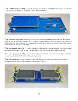
Страница 45: ...to the back of the front panel only one of these causes the LCDs to align correctly with the openings Orient the front panel board with the LCDs aligned with their openings and use the 4 40 X black screws to secure the PCB to the fromt panel Step 13 Power Switch Insert the power switch breaker into the opening from the front of the panel The front panel is now complete Get ready for final assembly...

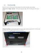
Страница 46: ... 500 amplifier support package Step 1 Power Supply Assembly Set the power supply assembly with the mounting plate on the top as shown Step 2 Front Panel Attach the front panel to the power supply assembly using four 6 32 3 8 black pan head screws Do not completely tighten the screws at this time ...

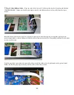
Страница 47: ...ribbon cable back across the connector and route the cable through the rectangular opening in the power supply plate as shown Make sure that the cable is flat and not twisted The polarity indicator on the cable can be on either side Turn the assembly on its side and connect the other end of the cable to the 10 pin header on the power board Make sure that the pins align correctly and the cable is f...

Страница 48: ... the power supply assembly with its mounting plate down as shown The LPF assembly has to slide under the front panel board Step 5 Front Panel Attach the front panel to the LPF assembly using four 6 32 3 8 black pan head screws Tighten all front panel screws ...

Страница 49: ...seated Make the following connections 1 The neutral wire single white wire terminal may be blue or red 2 The line distribution wire three black wires yellow terminal 3 The AC line from the inlet single black wire blue terminal Use the remaining zip tie to bundle the wires going to the power switch Step 7 Rear Panel Attach the rear panel to the power supply and LPF assembly using eight 6 32 3 8 bla...

Страница 50: ... rear panel here is the locations of the G round L ine and N eutral AC connections should already be in place chapter 12 step 9 Attach the AC line wire blue terminal with a single black wire and the AC neutral wire yellow terminal white with four white wires to the appropriate connection point on the AC inlet Plug the wire from the 80mm fan into the fan connection of the closest Meanwell If there ...

Страница 51: ... board and tighten the screws Route the free end of the wire through the rectangular hole adjacent to the power board Step 11 Connect 12V cables Plug the three 12V cables into the power board at the indicated locations The cables may be gray or red black All three locations are identical the cables may be plugged into any 12V connector ...

Страница 52: ...e under the 14 red black wires through the rectangular opening adjacent to the power board At this point the power supply section of the amplifier support kit is complete Please compare your unit to the picture below to ensure that everything in this section is connected properly ...

Страница 53: ... identical so use either fasten using 4 40 X black flat head screws red and install the press on rubber feet blue Step 14 Connect 12V cables Turn the unit over and connect the 12V cables The longest cable connects to the front panel board The other two cables are the same length Connect one to the LPF board and the other to the rear panel board ...

Страница 54: ... Cut a 10 25 5cm piece of RG 316 small brown coaxial cable Strip 12mm of the outer jacket from both ends Be careful not to damage the shield wires Unbraid the outer shield with a toothpick or similar item and gather the shield wires to one side Remove 7mm of the dielectric from the center conductor With a soldering iron tin the exposed shield and the center conductor The dielectric and outer jacke...

Страница 55: ...ot so keep the solder at least 1 8 4mm away from the dielectric and outer jacket Form the shield so it will fit in the terminal blocks and trim the end Step 20 Amp In RF Jumper Cut a 9 23cm piece of RG 58 coax and prepare the ends in the same manner Step 21 Install RF Jumpers Install the four coaxial jumpers that you just made The terminal blocks must be opened by loosening the screws prior to ins...

Страница 56: ... of the heatsink and heat spreader may be sharp use care in handling these parts and consider wearing gloves during the next few steps Step 22 Thermal Pad Remove the plastic backing from one side of the thermal pad ...

Страница 57: ...pad save it it may be useful in other projects Using a utility knife trim the edges thermal pad to match the heatsink Step 23 Threaded Rods In each of the four corners of the heatsink insert the 4 40 x threaded rod through the thermal pad into the heatsink Lift the corner of the heatsink and apply thread locker if desired Thread the rod into the heatsink until the end of the rod comes through the ...

Страница 58: ...mine where the holes in the heatsink are Make sure that you have the right side up You can see the holes in the heatsink from the fin side and align the heat spreader correctly on the heatsink If the alignment is correct a screwdriver placed in the large hole near the center will pass through the heat spreader through the thermal pad and through the heatsink If it doesn t turn the heat spreader ar...

Страница 59: ...rods the washer in the kits may be black Put a small amount of heatsink compound in the large hole in the center of the heat spreader If you haven t assembled the AN1819 board now would be a good time to do so Apply a small amount of heatsink compound to R23 on the AN1819 board ...

Страница 60: ...ur 4 40 hex nuts with integral lock washers red circles Place the VRF2933 MOSFETs in their proper locations aligning the drain tabs the tabs with the cut off corner with the D on the circuit board Secure the MOSFETs using four 4 40 X screws yellow circles Solder the tabs on the MOSFETs by patiently applying the soldering iron to the PCB next to the tab and applying a SMALL amount of solder to the ...

Страница 61: ... you are measuring C3 and meters react differently to large caps The gate tabs opposite the drain should read 10K to ground Step 28 Heatsink Assembly Place the heatsink assembly into the top of the amplifier support package and secure with four 6 32 X screws Step 29 Amplifier Cables Connect the RF Input green DC Input red and RF Output yellow cables Be sure that the ground and RF connections are c...

Страница 62: ...e Connect four pin amplifier control cable between the front panel board and the AN1819 board Congratulations you made it to the end Your amp is complete except for the top cover All we need to do is set the bias and you are ready to go ...

Страница 63: ... top cover removed The amplifier should be free from and test cables tools or debris Plug the amp in with a 14 gauge power cable directly into a wall socket do not use extension cords or outlet strips The performance of your amplifier depends highly on the quality of your AC supply If the AC voltage sags so will the output power Step 1 Powering the Hardrock 500 The first time you turn on the Hardr...

Страница 64: ...pots on the AN 1819 board are fully counter clockwise CCW Turning the bias on in the next step can damage the VRF2933 MOSFETs if the BIAS pots are not fully CCW Step 4 Set the Bias Touch SELECT in the center of the screen to activate the bias If the BIAS pots are set correctly you should see 0 mA if you see more than 10 mA press OK to turn off the bias ...

Страница 65: ...it down Pro Tip Nothing happens for a long time then the bias rises quickly turn slowly be patient Step 6 Adjust BIAS 2 Slowly turn the BIAS2 pot on the AN1819 board until the current reaches 250 mA above the setting obtained in step 5 Step 7 Complete Press EXIT to complete the settings Step 8 Top Cover Install the top cover and fasten using 4 40 X black flat head screws ...

Страница 66: ...IPTION PICTURE QUANTITY C3 680uF 80V 1 LM35 TEMPERATURE SENSOR 1 NTC THERMISTOR 100 OHMS 1 T1 RF400 CORE 1 T2 FT61 TOROID 0 63 19mm DIAMETER 1 T3 TYPE 61 BINOCULAR CORE 1 22 TEFLON WIRE 18 18 ENAMELED WIRE 18 25 OHM COAX CABLE 18 VRF2933 2 ...

Страница 67: ... by RF Power Tools C3 may not be installed Step 1 Trim Leads Carefully trim the leads of the terminal blocks VR1 and VR2 so that no more than 0 1 25cm projects from the bottom of the PCB The PCB mounts VERY close to the copper heat spreader so it is important to cut all leads on the bottom of the board as close as possible to prevent shorts Step 2 T1 Core Solder T1 s core to the AN1819 PCB One sid...

Страница 68: ...ide of C23 Trim any excess wire flush with the PCB You should see two wire loops on this end of the core and three loops on the other end of the core When trimming the wires on the bottom of the PCB remember to cut them flush with the PCB there is very little clearance between the PCB and the copper heat spreader Step 4 T2 Wire Prep Cut two 8 20 cm pieces of 18 enameled wire and one 5 13cm piece o...

Страница 69: ...ould conduct and the pair indicated with green should conduct but red should not conduct with green Step 6 Install T2 Once you have the leads aligned correctly insert the leads of T2 into the PCB The enameled wires are inserted into the larger hole in the footprint If these winding are correct the drain tabs of Q1 and Q2 indicated by a D on the PCB should conduct with the positive DC input Once yo...

Страница 70: ...CB and trim any excess flush with the PCB Wind the Teflon wire around T2 s core passing it through the core a total of three times Cut the wire strip the end and insert the wire into the remaining small hole in T2 s footprint Solder the wire to the PCB and trim any excess flush with the PCB Keeping in mind the very limited distance between the back of the PCB and the heat spreader ...

Страница 71: ...trip off 0 4 1 cm of the outer jacket from one end of each of the pieces Cut the shield so about 0 1 3mm of the braid remains exposed Strip 0 2 6mm the dielectric and tin the shied and exposed center conductor the outer jacket and dielectric are both Teflon so they will not melt ...

Страница 72: ...center conductor The pad is split with wider side for the shield and the narrow side for the center conductor Step 10 Wind T3 Place the rectangular core into the opening in the PCB with the holes in the core adjacent to the coax sections Pass the coax pieces through the holes in the core then around the outside of the core and through the hole again a total of three passes through the core ...

Страница 73: ...f the circuit board Strip the dielectric from the center conductors Step 11 Complete T3 Trim the wires and solder them to the pads With each center conductor going to one of the outer pads and both shields going to the center pad The shield of this coax is NOT at ground potential Do not touch the shield while the unit is operating and do not connect any portion of the shield to ground ...

Страница 74: ... and R13 are mounted on the back side of the PCB Insert U1 aligning the flat side of the component with the flat side indicated on the silkscreen R13 is not polarized just insert the leads into the holes and bend the component so the body is in the opening in the PCB Solder R13 and trim the excess leads The AN 1918 is now ready to mount on a suitable heatsink ...

Отзывы: