


8
FEaTURES FaMiLiaRizaTiOn
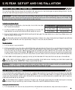
CHANNEL SLOT
FUNCTION
Channel Slot 1
Channel Slot 2
Channel Slot 3
Elevator
Aileron
Throttle/ESC
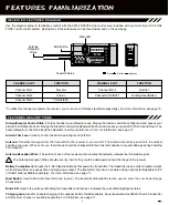
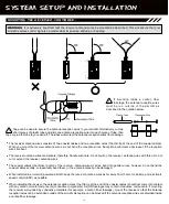
Use the diagram below to familiarize yourself with the 92124 RX500 5-Channel receiver included with your Aero Sport 5 2.4GHz
FHSS-1 radio control system. Descriptions of these features can be found below and on the next page.
REcEivER FEaTURES DiagRaM
CHANNEL SLOT
FUNCTION
Channel Slot 4
Channel Slot 5/BATT
Rudder
Landing Gear/Battery
*To utilize this channel and power the receiver, you must use a Y-Harness (available separately). For more information, see page 10.
Bind Button
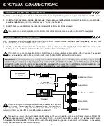
Coaxial Cables
Antenna
Reception
Wires
Bind LED
= Signal = Positive
= Negative
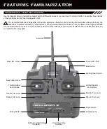
Aileron/Elevator Control Stick:
Controls the Aileron and Elevator axes. Moving the Aileron control stick Right and Left causes your
aircraft to Roll Right and Left. Moving the Elevator control stick Backward and Forward causes your aircraft to Pitch Up and Down. The
Aileron/Elevator control stick length is adjustable to suit your preference. For more information, see page 15.
Aileron Trim Lever:
Used to control
the Aileron axis Right and Left trim.
Antenna:
Transmits the signal from the transmitter to the receiver in your aircraft. The Antenna should be pivoted into the vertical
position during use. When not in use, the Antenna should be collapsed into the horizontal position to prevent damage during handling
and transport.
Antenna Reception Wires:
The portion of each of the receiver antenna wires that actually receives the transmitter signal.
The Antenna Reception Wires should never be bent or they could be damaged and limit the range of the receiver.
Battery Compartment:
Houses the 4 'AA' Alkaline batteries that power the transmitter. The transmitter uses 4 cells for lighter weight,
while still providing long usage time and high power output. The transmitter can also be powered using optional rechargeable Ni-Cd
or Ni-MH cells (available separately). For more information, see page 11.
Bind Button:
Used to Bind the transmitter and receiver. The transmitter Bind Button is also used to enter the Low-Power Range
Check mode.
Bind LED:
Used in the process of Binding the transmitter and receiver. Indicates the current Binding/Signal status.
Charging Jack:
Used for onboard charging of the optional Ni-Cd or Ni-MH batteries. An optional Airtronics 95035 110v AC Transmitter
and Receiver charger is available separately. For information, see page 11.
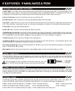
FEaTURES DEScRiPTiOnS
Содержание Aero Sport 5
Страница 1: ...1...


