Hobby People Aero Sport 5 Скачать руководство пользователя страница 15

15

When lengthening the control sticks, we strongly suggest that you leave at least four threads inside the top half of each control 

stick. This will ensure that the control sticks maintain optimum mechanical security. If you thread the control sticks out too far, 

the control sticks might come loose during use.

cOnTROL STick LEngTh aDjUSTMEnT

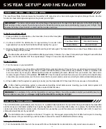
2)  Move the transmitter control sticks to the desired Fail Safe position. While holding the transmitter control sticks in those positions 

(generally throttle at idle and a minimal amount of elevator and/or aileron), press and hold the Bind Button on the receiver. 

After ~2 seconds, the Bind LED will begin to blink slowly. Continue holding the Bind Button until the Bind LED begins to blink 

rapidly (~2 more seconds). Once the Bind LED begins to blink rapidly, release the Bind Button.

3)  Turn the transmitter OFF to test the Fail Safe operation. The servos should move to the positions that you set in step 2.

FaiL SaFE PROgRaMMing, cOnTinUED....

SySTEM SETUP anD inSTaLLaTiOn

The Fail Safe settings will be erased if you re-bind the transmitter and receiver pair. If you bind the same transmitter and 

receiver pair you MUST repeat these procedures to setup the Fail Safe function again.

IMPORTANT

  If you don't program the Fail Safe function, if the signal between the transmitter and receiver is lost, the servos will 

stay in the last position they were in when the signal was lost. However, the servos will be free to move under load. They will not 

be locked in the last position they were in.

Clearing Fail Safe Settings

1)  To clear the currently programmed Fail Safe settings, re-bind the transmitter and receiver pair. For more information, see page 12.

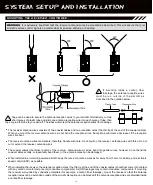
The length of the control sticks can be adjusted to best suit the way you hold them. In general, pilots who place their thumbs on top 

of the control sticks prefer the control sticks to be shorter, and pilots who grasp the control sticks prefer the control sticks to be longer.

1)   While holding the base of the control stick, turn the top half of the control stick counter-

clockwise to loosen it.

2)   To lengthen the control stick, turn the top half of the control stick counter-clockwise.

3)   Once your are satisfied with the length of the control stick, thread the bottom half of the 

control stick up and tighten it gently against the top half of the control stick.

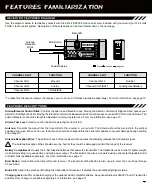
POwER LED anD LOw vOLTagE aLaRM

The Aero Sport 5 transmitter features a Power LED and an audible Low Voltage Alarm to indicate the current voltage status of the 

transmitter batteries. Use the information below to familiarize yourself with their use.

SAFE TO FLY

 - When both the Green LED and the Red LED are illuminated, and there is no audible Low Voltage Alarm sounding, the 

battery voltage is within the safe level to fly.

CAUTION/LAND

 - When the audible Low Voltage Alarm sounds and both the Green LED and the Red LED are illuminated, the battery 

voltage has dropped below the safe level (4.8 volts) and you should land immediately, then replace or recharge the transmitter batteries.

DO NOT FLY

 - When the audible Low Voltage Alarm sounds and the Red LED is illuminated and the Green LED is flashing, the battery 

voltage is so low that the transmitter signal has been compromised. If this occurs, 

DO NOT FLY!

 Replace or recharge the transmitter 

batteries. If you're flying when this occurs, the receiver Fail Safe function will Activate.

Содержание Aero Sport 5

Страница 1: ...1...

Страница 2: ...cautions Page 5 AMA Information Page 5 Features and Specifications Page 6 System Features Page 6 System Specifications Page 6 Servo Recommendations Page 6 Features Familiarization Page 7 Transmitter F...

Страница 3: ...tween the antenna the user s body is maintained Use of other accessories may not ensure compliance with FCC RF exposure guidelines We appreciate your purchase of the Hobby People Aero Sport 5 2 4GHz F...

Страница 4: ...uency control transmitter precautions l Turn the transmitter ON first and then turn the receiver ON After using your model turn the receiver OFF first then turn the transmitter OFF It can be dangerous...

Страница 5: ...during use Make sure that the receiver servos battery holder and switch harness connectors are securely fitted l The receiver is susceptible to vibration and moisture Take appropriate measures to prot...

Страница 6: ...42oz in 3 0kg cm 4 8v 53oz in 3 8kg cm 6 0v Speed 0 20 sec 60 4 8v 0 16 sec 60 6 0v Dimensions 1 54 x 0 79 x 1 42in 39 1 x 20 0 x 36 0mm Weight 1 59oz 45gr 94102Z Standard Bushing 94162Z High Torque...

Страница 7: ...or Control Stick Throttle Rudder Control Stick Rudder Trim Lever Throttle Trim Lever Aileron Trim Lever Elevator Trim Lever Power LED Red Bind LED Green Neck Strap Anchor The transmitter antenna is ad...

Страница 8: ...im Antenna Transmits the signal from the transmitter to the receiver in your aircraft The Antenna should be pivoted into the vertical position during use When not in use the Antenna should be collapse...

Страница 9: ...g gear or the flaps on your aircraft Servo Reversing Switches Used to electronically switch the direction of servo travel Servo Reversing is featured on the Elevator Aileron Throttle and Rudder channe...

Страница 10: ...Harness If you will not be using a servo plugged into channel slot 5 a Y Harness is not necessary Simply plug the switch harness into channel slot 5 If you prefer to use a rechargeable Ni Cd or Ni MH...

Страница 11: ...transmitter could be damaged WARNING An after market peak detection charger and or cycler should NOT be used to charge the optional rechargeable batteries through the transmitter The circuitry within...

Страница 12: ...illuminate solid green 4 Quickly press the Bind Button on the transmitter The Bind LED on the receiver will blink rapidly for 3 seconds go out momentarily then illuminate solid blue indicating the Bi...

Страница 13: ...rcraft keep the receiver antenna wires as far away from the motor battery and electronic speed control ESC as possible l When installing the receiver the antenna reception wires the thin tip at the en...

Страница 14: ...attery connections are correct and secure Check to ensure that the receiver antenna wires are correctly mounted as described previously 3 When satisfied that the system is operating correctly turn the...

Страница 15: ...d Fail Safe settings re bind the transmitter and receiver pair For more information see page 12 The length of the control sticks can be adjusted to best suit the way you hold them In general pilots wh...

Страница 16: ...annel mixing The Channel Mixing function allows you to quickly set up the transmitter s low level mixing based on the type of aircraft you re flying Options include Normal Delta Elevon and V Tail For...

Страница 17: ...sticks are moved to their stops that the servos do not buzz and that the control surfaces do not move any more than the maximum control throw necessary If the servos are buzzing this means that they...

Страница 18: ...ttery voltage Receiver antennas not mounted correctly in your model Transmitter antenna not angled to optimum position Transmitter in Low Power Range Check mode Incorrect Servo Reversing switch positi...

Страница 19: ...dulation type which transmits data across the entire frequency spectrum by transmitting data on different channels at an extremely fast interval Landing Gear Switch Used to control the operation of th...

Страница 20: ...duct For More Information or Product Service Contact Global Services 18480 Bandilier Circle Fountain Valley CA 92708 Telephone 714 963 0329 Fax 714 964 6236 Email service globalhobby net http globalse...

Отзывы: