Last updated: 08/13/20108 Rev. 9
45
Connections:
Step 1:
Connect all stepper motors to the X, Y, (if using a gantry style machine Y2) and Z. The 6 pin connectors
are labelled below. Looking at the face of the box the connections are, from left to right:
Accessories :
Black/ White = Z probe Yellow/Blue = (+/-) PWM Red/Green = (+/-) 0-
10V
X Axis:
Black/White = X axis limit switch Yellow/Blue = 1A 1B stepper motor pair Red/Green 2A/2B
Y Axis:
Black/White = Y axis limit switch Yellow/Blue = 1A 1B stepper motor pair Red/Green 2A/2B
YNL: (this is only needed on gantry style machines with two Y motors)
YNL stands for Y axis no limit, the black and white wires are not present on this axis.
Yellow/Blue = 1A 1B stepper motor pair Red/Green 2A/2B
Z Axis:
Black/White = Z axis limit switch Yellow/Blue = 1A 1B stepper motor pair Red/Green 2A/2B
NOTE: If your machine is a kit from us this will directly plug (color to color) into the stepper motors and limit
switches.
NOTE: All limit switches are filtered and should be used in the NO (Normally Open) position.
Содержание R7
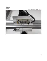
Страница 6: ...Last updated 08 13 20108 Rev 9 6 Limit switch and barrier block shown installed ...
Страница 19: ...Last updated 08 13 20108 Rev 9 19 ...
Страница 27: ...Last updated 08 13 20108 Rev 9 27 ...
Страница 28: ...Last updated 08 13 20108 Rev 9 28 ...
Страница 30: ...Last updated 08 13 20108 Rev 9 30 ...
Страница 32: ...Last updated 08 13 20108 Rev 9 32 ...

