Hobbico Hobbistar 60 MK III Скачать руководство пользователя страница 20

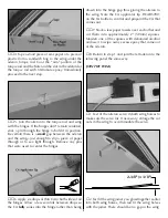
BALANCE THE MODEL (C.G.)

At  this  time  the  model  must  be  in  “ready-to-fly”
condition  with  all  components  installed  including
the  complete  radio  system,  landing  gear,  engine,
prop and spinner. The model is to be balanced with
the fuel tank empty.

1.  If  using  a  Great  Planes

®

C.G.  Machine

to

balance  the  model,  set  the  rulers  to  3"  [76mm].  If
you do not have a Great Planes C.G. Machine, use
a felt-tip pen or 1/16" to 1/8" [1.5 to 3mm] tape to
accurately  mark  the  C.G.  3"  [76mm]  from  the
leading edge on the bottom of the wing.

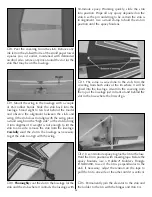
2. Mount the wing to the fuselage with at least four

#64 rubber bands. If using a C.G. Machine, place the
model on the machine. If not using a C.G. Machine, use
the tip of your middle fingers on both hands to lift the
model by the wing on both sides of the fuselage at the
balance point you marked on the bottom of the wing.

3. If the fuselage is level when lifting the model the

C.G. is correct. If the nose drops the model is nose-
heavy and will require weight on the tail to balance.

This is where the model should balance for the first
flights. Later, you may wish to experiment by shifting
the C.G. up to 1/2" [13mm] forward or 1/2" [13mm]
back to change the flying characteristics. Moving the
C.G. forward will increase stability, but will decrease
the  model's  aerobatic  capabilities  by  decreasing
maneuverability.  Moving  the  C.G.  aft  will  have  the
opposite effect. In any case, as long as the model is
balanced 

within the recommended range

it will not

display  any  bad  tendencies.  Do  not  at  any  time
balance the model outside the recommended range.

More  than  any  other  factor,  the 

C.G.

(center  of

gravity,  also  referred  to  as  the  balance  point)  can
have the 

greatest

effect on how a model flies and

may determine whether or not the first flight will be
successful.  If  the  plane  is  nose  heavy  it  could  be
difficult to takeoff and land and lose some of its self-
recovery  capabilities.  If  the  plane  is  tail  heavy  the
controls  may  be  too  sensitive,  making  the  model
overreact to control inputs. If you value this model
and  wish  to  enjoy  it  for  many  flights, 

DO  NOT

OVERLOOK  THIS  IMPORTANT  PROCEDURE.

A

model that is not properly balanced will be unstable
and possibly unflyable.

Prepare the Model for Flying

20

Содержание Hobbistar 60 MK III

Страница 1: ...ssembled product the user accepts all resulting liability If the buyer is not prepared to accept the liability associated with the use of this product the buyer is advised to return this kit immediately in new and unused condition to the place of purchase ASSEMBLY INSTRUCTIONS TM Copyright 2003 HCAZ3064 for HCAA2125 V1 1 Specifications Wingspan 71 in 1805mm Wing Area 888 sq in 57 dm2 Weight 7 8 lb...

Страница 2: ...leshooting to figure out how to get the model to fly Under the guidance of a flight instructor all you ll have to do is concentrate on learning to fly And after you ve mastered the Hobbistar the engine and radio may be installed in your next model IMPORTANT The best thing you can do to insure success is to find a flight instructor who will inspect your model for airworthiness and provide flying le...

Страница 3: ...th the help of a competent experienced R C pilot These are the items not supplied with the Hobbistar 60 MKIII that must be purchased separately Where appropriate order numbers are provided in parentheses RADIO SYSTEM A 4 channel radio control system with four servos is required to fly the Hobbistar 60 MKIII 4 channels means that the radio is capable of operating four controls On a trainer model su...

Страница 4: ...items are not absolutely required but are mentioned in the instructions and will help you assemble the Hobbistar 60 MKIII Top Flite MonoKote sealing iron TOPR2100 Top Flite Hot Sock iron cover TOPR2175 4 oz 113g aerosol CA activator GPMR634 CA applicator tips HCAR3780 CA debonder GPMR6039 Epoxy brushes 6 GPMR8060 Mixing sticks 50 GPMR8055 Mixing cups GPMR8056 Builder s Triangle Set HCAR0480 Pliers...

Страница 5: ... gear mount 2 2mm x 9 7 8 250mm threaded one end wire aileron pushrods 1 2mm x 27 685mm threaded one end wire throttle pushrod 1 2mm x 19 3 4 500mm wire nose wheel steering pushrod 2 nylon aileron torque rod horns 2 nylon straps main landing gear 5 nylon clevises 5 nylon pushrod keepers 2 nylon control horns w mnt plates 5 silicone retainers for clevises 15 precut CA hinges 4 4 x 25mm Phillips hea...

Страница 6: ...obby supplier Parts listed below Contact your hobby supplier HCAA3120 Fuselage Set Fuselage servo tray wing dowels 2 HCAA3121 Wing Set Right left wing panels w ailerons hinges 8 plywood wing joiners 3 aileron servo tray HCAA3122 Tail Set Fin rudder stab elevator hinges 7 HCAA3123 Landing Gear Set 5mm main gear wires 2 4mm nose gear wire 5mm wheel collars screws 4 4mm wheel collars screws 2 The Hob...

Страница 7: ... to apply epoxy to all mating surfaces In other words apply epoxy to both sides of the joiner in the middle and to the inside of both the joiner on the top and the joiner on the bottom Hold the joiners together with clamps Wipe away excess epoxy before it hardens 2 Round the ends of both 1 4 6 5mm wing dowels Cut the covering from the holes in the fuselage for the dowels and glue them into positio...

Страница 8: ...nrestricted movement of the rod 2 Test fit the aileron to the wing with four CA hinges but do not glue them in yet If it is difficult to join the aileron to the wing because the hinge slots are too tight remove the hinges Widen the hinge slots by inserting a 11 blade and moving it back and forth a few times 3 Remove the aileron from the wing Drill a 3 32 2 4mm hole 1 2 13mm deep in the center of t...

Страница 9: ...low a few seconds between drops so the CA fully soaks into the hinge rather than being drawn into the hinge gap thus gluing the aileron to the wing Note the CA applicator tip HCAR3780 on the CA bottle to control and pinpoint the CA that comes out 7 Stack a few paper towels over each other and cut them into approximately 2 50mm squares Moisten one of the squares with denatured alcohol and use it to...

Страница 10: ...4 Coat the inside and the end of the other wing with 30 minute epoxy Also coat the end of the joiner that is sticking out of the other wing half Fit the wings together 5 Tightly hold both wing halves together with several strips of masking tape on both the top and bottom of the wing Be certain the leading and trailing edges of the wing align As you apply the tape wipe away excess epoxy that comes ...

Страница 11: ...erline on the trailing edge remains centered in the fuselage 6 Use a fine point felt tip pen such as a Top Flite Panel Line Pen TOPQ2510 to mark the outline of the fuselage on the top and bottom of the stab 7 Remove the stab from the fuse Use a sharp 11 hobby knife or follow the ExpertTip below to cut the covering from the stab along the lines Use care to cut only into the covering and not into th...

Страница 12: ...fuselage for the stab and the stab where it contacts the fuselage with 30 minute epoxy Working quickly slide the stab into position Wipe off any epoxy deposited on the stab Use the pin and string to be certain the stab is in alignment Use a small clamp to hold the stab in position until the epoxy hardens 11 The same as was done to the stab trim the covering from both sides of the fin where it will...

Страница 13: ...ck washers Be certain to securely tighten the screws using a 2 Phillips screwdriver 5 Mount the nose wheel to the nose gear wire with a 4mm wheel collar and a 3 x 5mm screw on both sides of the wheel The same as the main wheels be certain to file a flat spot on the wire for the outer wheel collar and add a drop of oil to both sides of the wheel to help it spin freely Refer to this photo for the fo...

Страница 14: ...all If necessary bend the front of the pushrod to align with the connector then cut the pushrod to the correct length Temporarily fasten the pushrod to the connector with a 3 x 5mm screw 12 Mount the wing to the fuselage with two 64 rubber bands Place the model on its landing gear Set the engine or anything heavy enough to hold the front end down on the engine mount View the model from the side Ra...

Страница 15: ...ank when the assembly is installed in the tank 4 Fit the fuel line to the short aluminum tube Cut the fuel line to the correct length so that when the fuel line weight clunk is installed it will be near but not contacting the back of the tank Otherwise the line may become stuck above the fuel level discontinuing fuel flow 5 Note that the tube in the right side of the tank is the pressure line that...

Страница 16: ... It may be necessary to enlarge the holes in the servo arm to fit the pushrod If so use a hobby knife with a 11 blade to carefully enlarge the holes from both sides of the arm 7 Connect the other pushrod to the servo arm and the torque rod the same way 8 Center the servo arm Adjust the length of the pushrods by turning the clevises in or out until both ailerons are centered HOOK UP THE CONTROLS Re...

Страница 17: ...m drill Refer to this photo while connecting the pushrods to the servos 9 Make a 90 degree bend in the elevator pushrod so the elevator will be centered when the pushrod is connected to the servo arm This is most easily done by disconnecting the pushrod from the elevator rotating the pushrod 90 degrees then making the bend to the side The clevis on the back of the pushrod will now have to be turne...

Страница 18: ... glue pieces of the 1 4 x 1 2 6 x 13mm balsa stick to the fuselage sides across the receiver and battery to securely hold them down Make certain nothing interferes with the movement of the throttle or nose wheel steering pushrods Cut the covering from the square hole in the left side of the fuselage for the on off switch Drill two 3 32 2 4mm holes for the switch mounting screws and mount the switc...

Страница 19: ...andle the line for filling the fuel tank as the tank is filled through this line 3 Fit the back plate of the spinner and a suitable propeller to the engine If the hole in the back plate and prop are too small use a prop reamer or the correct size drill to enlarge the holes a 5 16 drill is suitable for engines that have a 5 16 24 crank shaft such as the O S MAX 65 LA A prop reamer is best as it sel...

Страница 20: ...re the model should balance for the first flights Later you may wish to experiment by shifting the C G up to 1 2 13mm forward or 1 2 13mm back to change the flying characteristics Moving the C G forward will increase stability but will decrease the model s aerobatic capabilities by decreasing maneuverability Moving the C G aft will have the opposite effect In any case as long as the model is balan...

Страница 21: ... epoxy If tail weight is required do not simply adhere the lead to the covering Instead use a pin to poke several holes in the covering over the left side of the fuselage opposite the engine exhaust under the stabilizer Add several drops of thin CA to the area to thoroughly bond the covering to the wood Now the lead may be stuck to the fuselage Be certain any weight stuck to the tail does not inte...

Страница 22: ... pushrod Note Be sure not to unscrew the clevis too far It must remain securely fastened to the end of the pushrod 2 Center the rudder and both ailerons the same way 3 Now that the rudder is centered center the nose wheel by adjusting the pushrod in the threaded connector on the steering arm Roll the fuselage along a flat surface such as your garage basement or kitchen floor to make certain it rol...

Страница 23: ...all the way up but leave the throttle stick all the way down Now the carburetor should be partially open about 1 32 to 1 16 1 to 1 5mm 4 Move the throttle stick all the way up The carburetor should be fully open If the carb is not fully open the pushrod travel may have to be increased This is done by moving the clevis further out on the servo arm or by moving the pushrod connector closer in on the...

Страница 24: ...on and rudder control throws the same way IDENTIFY YOUR MODEL Whether you fly at an R C club or somewhere on your own you should have your name telephone number and address in or on your model so it can be identified and returned in case it lands somewhere away from the flying site Fill out the I D tag found at the end of the manual and place it on or inside the model BALANCE PROPELLERS To inexper...

Страница 25: ...rteen rubber bands are suggested Be certain the final two are crisscrossed thus ensuring that the others remain secure IMPORTANT Your radio control system transmits a signal on a certain frequency Be certain you know what the frequency is This is expressed as a two digit number 42 56 etc and can be found on the container the radio system came in and is also located on the transmitter and receiver ...

Страница 26: ...transitions smoothly and rapidly to full power and maintains full power indefinitely After you run the engine on the model inspect the model closely to make sure all screws remained tight the hinges are secure the prop is secure and all pushrods and connectors are secure Keep all engine fuel in a safe place away from high heat sparks or flames as fuel is very flammable Do not smoke near the engine...

Страница 27: ... Further these flight instructions may be referenced once you finally do begin flying on your own CAUTION THIS APPLIES TO ALL R C AIRPLANES If while flying you notice an alarming or unusual sound such as a low pitched buzz this may indicate control surface flutter Flutter occurs when a control surface such as an aileron or elevator or a flying surface such as a wing or stab rapidly vibrates up and...

Страница 28: ... 60 MKIII should fly well at half or even slightly less than half throttle Adjust the trims so the plane flies straight and level at your cruise throttle setting After flying around for a while and while still at a safe altitude with plenty of fuel practice slow flight and execute practice landing approaches by reducing the throttle further to see how the model handles when coming in to land Add p...

Отзывы: