❏
1. Prepare the prebent 3/16" [4.8mm]
forward
and
aft main landing gear wires
for
soldering and painting by cleaning them with
denatured alcohol or other suitable solvent.
Thoroughly
sand the wires with medium-grit
sandpaper, followed once again by wiping with
denatured alcohol. Use a file or a rotary tool
with a cutoff wheel to remove any burrs from
the ends of all the wires.
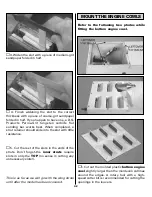
❏
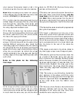
2. Tightly tape the horizontal wires of the
forward landing gear wire
together as shown.
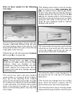
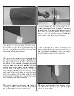
Refer to this photo for the following
three steps.
❏
3. Drill 1/16" [1.6mm] holes in the forward
landing gear block for the screws that hold the
nylon landing gear straps. Bolt the bottom wing
onto the fuselage, then place both landing gear
wires on the model. With the forward landing
gear wire in the groove, mount the landing gear
straps to the forward landing gear block with
four #2 x 1/2" [12.7mm] screws.
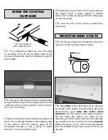
❏
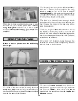
4. Tape one side of the aft wire to the forward
wire. Use a few drops of thin CA and
accelerator if necessary to tack-glue the other
side of the aft wire to the forward wire.
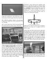
❏
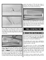
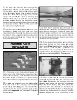
5. Make a 90° bend about 1/4" [6.4mm] from
one of the 36" [915mm] pieces of the thin
reinforcement wire included with this kit. Tuck
the bent end of the wire between two of the
landing gear wires (indicated by the arrow in
the photo), then tightly wrap the rest of the wire
around the landing gear.
❏
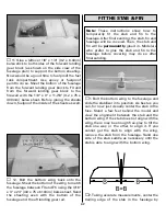
6. Continue to
neatly
and
tightly
wrap the
wire around the landing gear until there are just
a few inches left. Insert the end of the wire back
through the wire wrapped around the gear,
then pull tight with a pair of pliers. Cut off the
excess wire.
❏
7. Flip the model right-side-up. Add several
drops of soldering flux that comes with silver
solder to the area to be soldered. Heat the area
with a torch and add silver solder. Make certain
to use
silver solder
, not regular electrical
solder. While the joint is still hot, carefully turn
the model back over and inspect the bottom. If
necessary, add more flux and solder while
heating the joint. Do not add excess solder until
it drips from the joint. Allow the joint to cool.
After the solder has hardened, but while it is
MOUNT THE MAIN
LANDING GEAR
40
Содержание Dynaflite S.E.5a
Страница 9: ...9 Die Drawing...
Страница 10: ...10 Die Drawing...


