


BACnet Server
– Modbus Client
User Manual r1.10 eng
© HMS Industrial Networks S.L.U - All rights reserved
This information is subject to change without notice
URL
http
s
://www.intesis.com
31 / 41
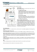
Connection to Modbus
6.3.1 Modbus TCP
Connect the communication cable coming from the network hub or switch to the ETH port of Intesis. The cable to be
used shall be a straight Ethernet UTP/FTP CAT5 cable.
6.3.2 Modbus RTU
Connect the communication cable coming from the Modbus network to the port/s marked as Modbus of Intesis.
Connect the EIA485 bus to connectors A3 (A-), A4 (B+) and A1 or A2
(SNGD) of gateway’s PortA. Respect the
polarity.
If you use Port B as a Modbus RTU port, connect the EIA485 bus to connectors B1 (B+), B2 (A-) and B3 (SNGD) of
gateway’s PortB. Respect the polarity.
Remember the characteristics of the standard EIA485 bus: maximum distance of 1200 meters, maximum 32 devices
connected to the bus, and in each end of the bus it must be a termination resistor of 12
0 Ω. The gateway has an
internal bus biasing circuit that incorporates the termination resistor. If you install the gateway in one of the ends of
the bus, then do not install an additional termination resistor in that end.
Note:
Modbus RTU only available when port B not used for BACnet MSTP integration. Selectable by Intesis MAPS.
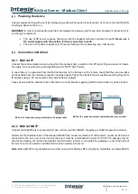
Connection to the configuration tool
This action allows the user to have access to configuration and monitoring of the device (more information can be
found in the configuration tool User Manual). Two methods to connect to the PC can be used:
•
Ethernet:
Using the Ethernet port of Intesis.
•
USB:
Using the console port of Intesis, connect a USB cable from the console port to the PC.


