


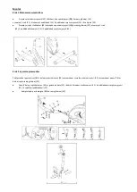

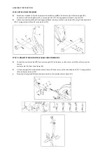


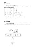
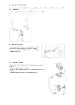


STEP 3 ATTACH THE LOWER SWING HANDLEBAR
⚫
Slide sleeve (18) and adjust washer (15) onto left horizontal axle, followed by left lower swing handlebar (17L),
washer (14), spring washer (13), secured with allen head bolts (12).
Repeat process for right hand side lower swing handlebar (17R) assembly.
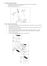
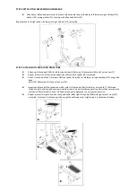
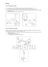
STEP 4 ATTACH FOOT PEDAL AND PEDAL TUBE
⚫
Attach right foot pedal (26R) to left foot pedal tube (46R) using 2 flat washers (45) and 2 nylock nuts (7)
⚫
Repeat process for left hand side pedal tube (46L) and foot pedal (26L) assembly.
⚫
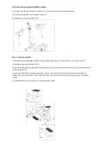
Attach front end welded U bracket of left foot pedal tube (46L) to left lower swing handlebar (17L) using allen
head
bolts (25), flat washer (24) and nylock nut (23).
⚫
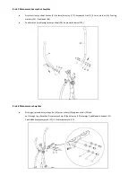
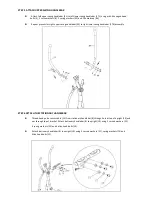
Important: Attach left foot pedal tube (46L) with left foot pedal (26L) to left arm of crank (67). The thread
stud has a left hand thread and screws into the crank in an anti-clockwise direction, this is then secured with
nylock nut (79L) which also has a left hand thread and is tightened in an clockwise direction.
⚫
Repeat process for right hand side foot pedal tube (46R), right foot pedal (26R) with right arm of crank (67)
assembly. Note that the thread parts have right hand threads and is tightened in a clockwise direction.
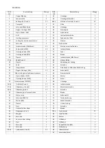
Содержание H2205
Страница 1: ...H2205 ...
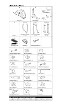
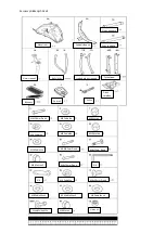
Страница 3: ...Lista załączonych części ...
Страница 9: ...Diagram zbiorczy ...
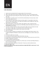
Страница 11: ...PRE ASSEMBLY CHECK LIST ...
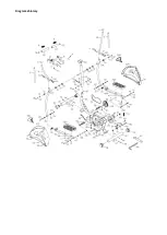
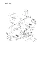
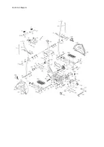
Страница 17: ...Exploded drawing ...
Страница 25: ...Souhrnný diagram ...
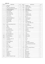
Страница 27: ...Stückliste ...


