Modbus Interface 4-9
© 2012 HMS Industrial Networks AB
Doc.Id. HMSI-168-25
Diagnostic Registers
Due to the fact that many Modbus devices do not support the diagnostic functions
(function 8), the diagnostic information has been made available at a special range
of register addresses to allow it to be accessed using the register read and write
functions. Every operation that is available through the function 8 interface is also
available using common register functions.
Note:
Do not confuse these registers with the J1939 diagnostic tables. These reg-
isters contain diagnostics for the module itself and its network interfaces.
Note:
The Swap I/O Bytes option does not have any effect on the diagnostic and
status registers. All diagnostic and status registers are in little endian format.
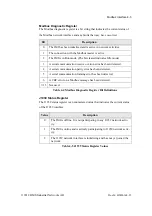
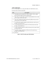
The following register addresses are defined to retrieve diagnostic information
from the JMI. They can be read using Modbus function 4.
functions” on page 4-3 for an explanation of each diagnostic value.
Register
Description
32001
Modbus diagnostic register.
32002
Modbus bus message counter.
32003
Modbus communication error counter.
32004
Modbus exception response counter.
32005
Modbus slave message counter.
32006
Modbus no response counter.
32007
Modbus receive overrun counter.
32008
J1939 status register.
32009
J1939 fault register.
32010
J1939 CAN error counter.
32011
J1939 CAN bus-off counter.
32012
J1939 CAN receive overrun counter.
Table 4-7 Input Register Addresses for Diagnostics

