Modbus Interface 4-3
© 2012 HMS Industrial Networks AB
Doc.Id. HMSI-168-25
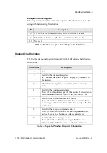
Exception Status Register
The exception status register returned in response to Modbus function 7 is a bit
string with the following bit definition.
Diagnostic Subfunctions
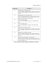
The Modbus diagnostic function (function 8) in the JMI supports the following
subfunctions.
Bit
Description
0
The JMI has been initialized and is active in network activities.
1
The JMI is in Run mode. (The bit cleared indicates Idle mode)
2-7
Not used.
Table 4-2 Modbus Exception Status Register Bit Definitions
Subfunction
Description
0
Echo.
2
Read Modbus diagnostic register.
See “Modbus Diagnostic Register” on page 4-5 for details on
this register.
10
Clear diagnostic registers and counters, and reset module
faults.
11
Read Modbus bus message counter.
This is the number of messages that the module has detected on
the Modbus network since bootup or the last counter reset.
12
Read Modbus communication error counter.
This is the number of CRC errors that have occurred in Mod-
bus messages addressed to the module since bootup or the last
counter reset.
13
Read Modbus exception response counter.
This is the number of Modbus exception responses that the
module has sent since bootup or the last counter reset.
14
Read Modbus slave message counter.
This is the number of Modbus messages that have been
addressed to the JMI since bootup or the last counter reset.
Table 4-3 Supported Modbus Diagnostic Subfunctions


