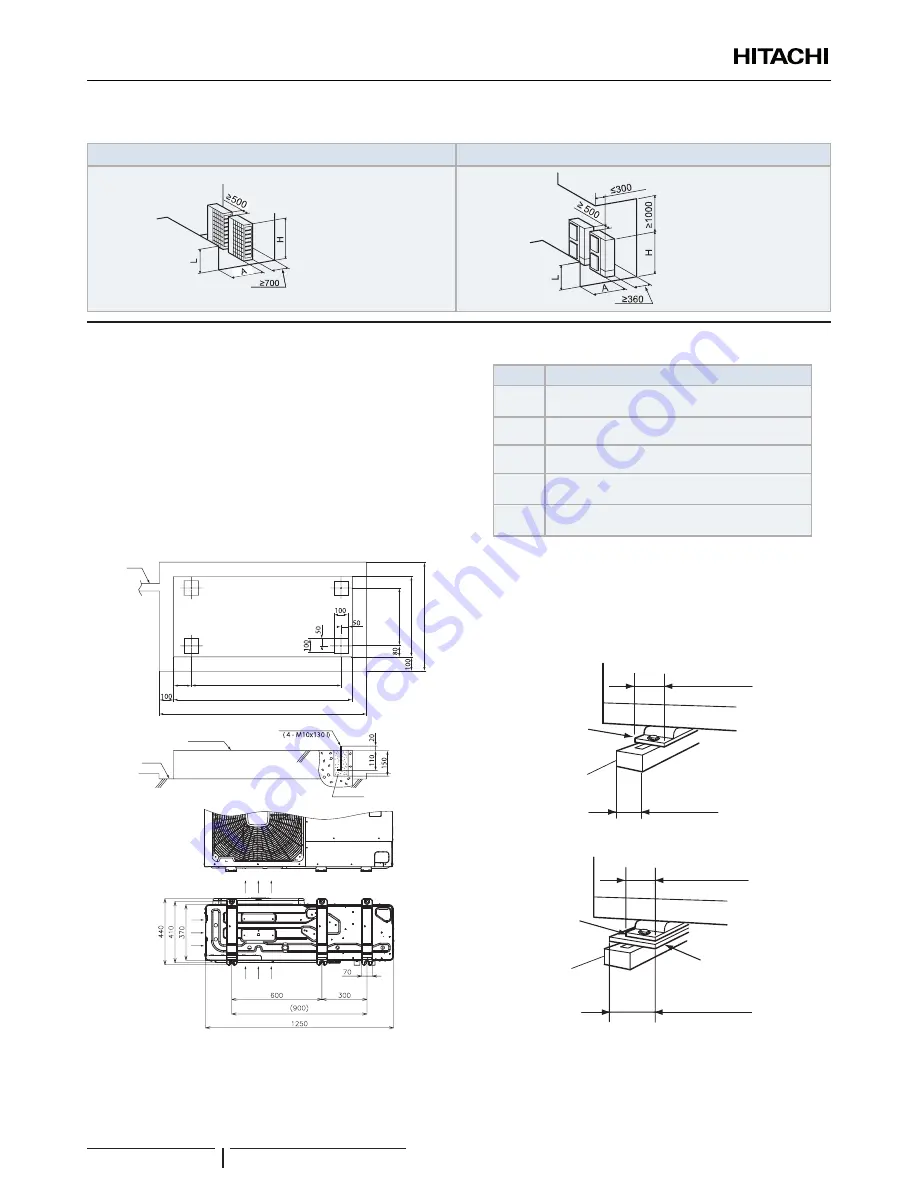
(Unit: mm)
Around sides are open
Around sides are open with obstacles above
0<L≤1/2H→A≥350
1/2H<L≤H→A≥450
H=1380
0<L≤1/2H→A≥600
1/2H<L≤H→A≥1200
H=1380
6.2 PLACE PROVISION
Concrete foundation
• Foundation shall be on a level surface and it is
recommended to be 100-300 mm higher than ground level.
•
Use M10 anchor bolts to fix the unit to the foundation.
(Foundation bolts, nuts and washers are not included, and
must be field supplied).
• Drain water might turn into ice on cold weather areas.
Therefore, when installing the unit on a roof or a veranda,
avoid the draining on a public area since it may become
slippery.
900
1250
1450
174
410
440
640
Nº
Description
Drain water
Drain water place
Concrete base
Foundation bolt
Mortar charge
• The whole of the base of the Yutaki M unit should be
installed on a foundation. When using vibration-proof mat,
it should also be positioned the same way. When installing
the Yutaki M unit on a fieldsupplied frame, use metal plates
to adjust the frame width for stable installation as shown in
below figure.
57 mm
Base width of Yutaki M unit
Yutaki M unit is
unstable
Frame
60mm
Frame with
(Field supplied)
INCORRECT
CORRECT
Yutaki M unit is
stable
57 mm
Base width of Yutaki M unit
Frame
100mm or more
Metal plate
Recommended Metal Plate Size
• (Field-Supplied) Material: Hot-Rolled Mild Steel
• Plate (SPHC) Plate Thickness: 4.5 T
UNIT INSTALLATION
PMML0342B rev.1 - 03/2016
8


