


--- 31 ---
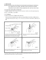
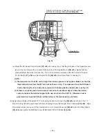
Fig. 17
Apply silicone rubber.
Position the blade of Dust
Guard Fin (B)
[29] <24>
under the rib of housing (A).
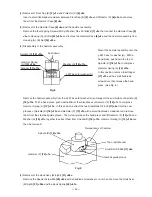
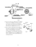
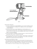
(3) Mounting the mechanical parts
(a) Mount Washer (S)
[16] <11>
onto Spindle (D)
[18] <13>
and mount the Hammer (F)
[12] <7>
containing
the twenty-eight Steel Balls D3.175
[13] <8>
, Washer (J)
[14] <9>
and Hammer Spring (A)
[15] <10>
to Spindle (D)
[18] <13>
.
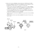
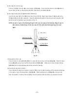
(b) Align the top of the cam groove on Spindle (D)
[18] <13>
with the steel ball guide groove on the
Hammer (F)
[12] <7>
as illustrated in Fig. 9. Press down either of the raised faces of the Hammer (F)
[12]
<7>
with a hand press to compress Hammer Spring (A)
[15] <10>
until the end surface of the Hammer (F)
[12] <7>
contacts Spindle (D)
[18] <13>
.
(c) Insert the two Steel Balls D 5.556
[11] <6>
into the steel ball guide groove. Check that the steel balls are
properly inserted in the cam groove. Then release the hand press.
(d) Mount the hammer assembly onto the J297 base for washer (S). With a hand press, push down the top of
Spindle (D)
[18] <13>
to compress Hammer Spring (A)
[15] <10>
. On this condition, mount the Stopper
[17] <12>
onto the spindle shaft and then release the hand press.
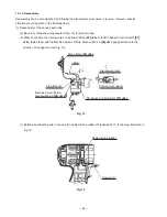
(4) Mounting the hammer assembly to the housing
Raise the housing assembled in step (2) and mount the hammer assembly to the housing being careful of
proper engagement between the Idle Gear Set
[19] <14>
of the hammer assembly (check that Washer (E)
[22] <17>
is mounted on Spindle (D)
[18] <13>
) and Ring Gear (C)
[21] <16>
. After mounting, check that the
hammer assembly turns. If the hammer assembly does not turn, the gears engage improperly.
Terminal support
Содержание WH 9DMR
Страница 46: ... 4 ITEM NO CODE NO DESCRIPTION REMARKS NO USED 4 05 WR 9DMR Printed in Japan 050401N ...
Страница 47: ......