background image


11.  

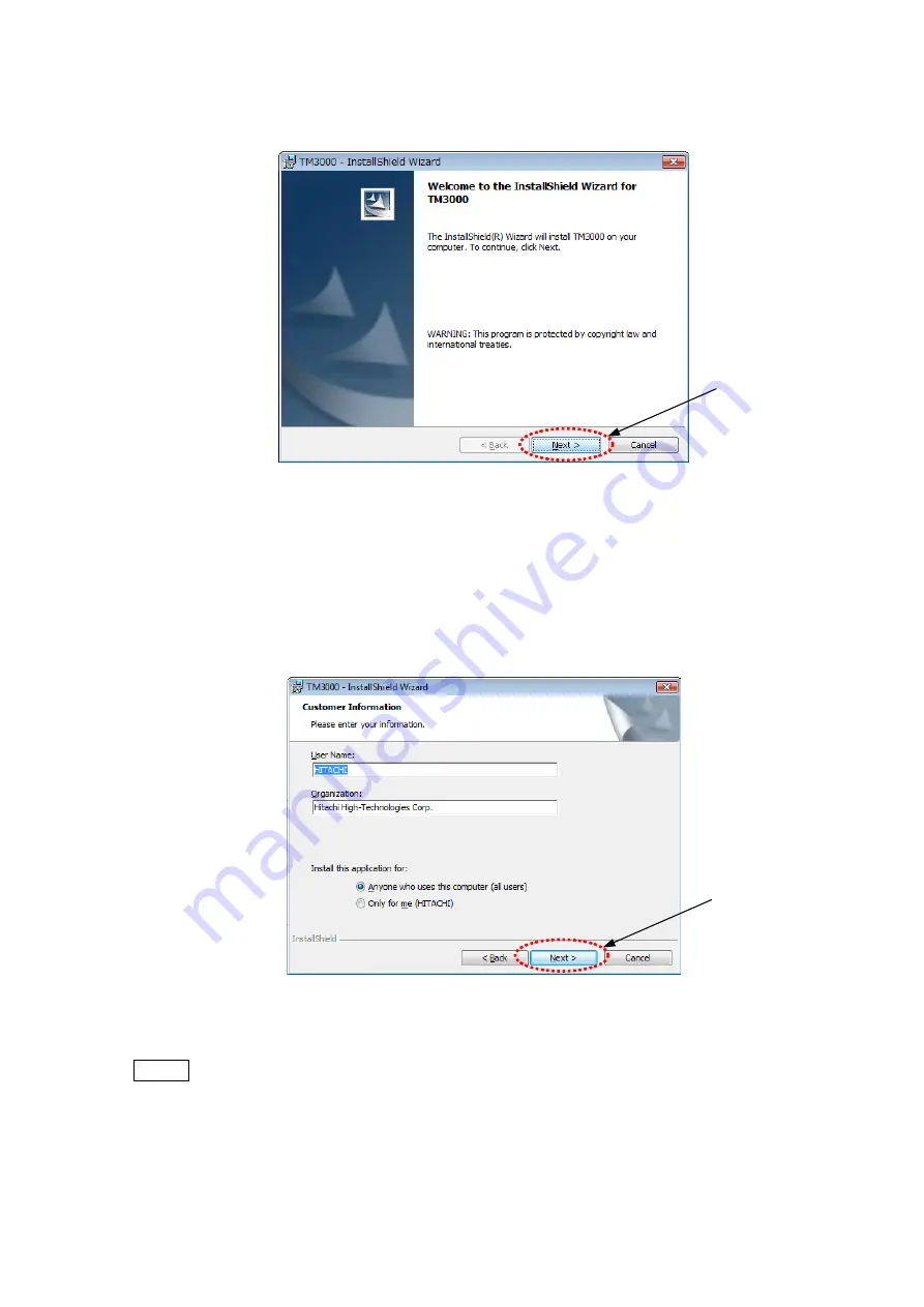
The following window appears. Click the [Next>] button. 


Click 


Figure 2.2.1-11  InstallShield Wizard 


12.  

The following window appears. Enter the [User Name:] and [Organization:]. It is 

information recorded to a PC that it is displayed by default. No change is OK. 

Verify that [Anyone who uses this computer (all users)] is selected in [Install this application 

for:]; click the [Next] button 


Click 


Figure 2.2.1-12    User Information Entry Window 


NOTE

  : If the TM3000 application is for all login users on the PC, select [Anyone who uses 

this computer (all users)]. 

The [Only for me] option excludes users other than the one who is performing the 

installation from using the TM3000 application.


2 - 6


Содержание TM3000

Страница 1: ...and precautions carefully Be sure to follow the instructions and warning of instruction manual and warning label Keep this manual in a safe place nearby so it can be referred to whenever needed Copyright C Hitachi High Technologies Corporation 2010 All rights reserved Printed in Japan Part No 55E 9001 1 HT R H HMS ...

Страница 2: ...arty in any form or by any means without the express written permission of Hitachi High Technologies Corporation 3 Hitachi High Technologies Corporation assumes no liability for any direct indirect or consequential damages arising from use not described in this manual Utmost care must be exercised when using the instrument 4 This document does not provide any warranty or permission for industrial ...

Страница 3: ...an take unexpected action out of curiosity the system administrator should use utmost caution to ensure that the safety tips are complied with and the system is not handled in a manner departing from the range of operations provided in the Instruction Manual Also securely control the system so that minors will not use the system on a solo basis ABOUT THIS INSTRUCTION MANUAL This Instruction Manual...

Страница 4: ...stem provided at the beginning of this Instruction Manual List of Abbreviations Abbreviations that appear frequently in this Instruction Manual and their full spellings are given below PC Personal Computer HV High Voltage DFP Diaphragm Pump TMP Turbo Molecular Pump FOV Field of View ...

Страница 5: ...sumables or parts with a limited warranty period that have failed after the warranty period Geographic Area of Warranty The warranty is limited to within the borders of the country in which the product was purchased Warranty Period The warranty period is one 1 year from the completion date of installation Warranty Limitations and Exclusions HHT does not extend any warranty either implicitly or exp...

Страница 6: ...d 9 A system failure arising from disassembling or alteration not authorized by HHT 10 A system that has been discarded or sold or relocated without notice to HHT or a system that is bought from a reseller 11 A system failure arising from the use of the system or by an operating method not provided in this Instruction Manual or from a repair performed not under HHT s control 12 A system failure ar...

Страница 7: ...e service company designated by HHT and request for the performance of a relocation service After Service 1 For any after service requirements please contact the HHT s dealership 2 Any system relocated or sold without contacting in advance the sales department that handles your account or a maintenance service company designated by HHT will be ineligible to receive after service 3 For a period of ...

Страница 8: ... relevant laws and directives can conceivable occur in the future when discarding the system either do so by checking relevant laws and regulations or consult the sales department that handles your account or a maintenance service company designated by HHT When discarding a used PC or turning it over for recycling please be sure to erase any data remaining on the hard disk at the customer s respon...

Страница 9: ...customer s responsibility 2 The chemicals should be handled stored and disposed of according to the instructions provided by their suppliers Electromagnetic Wave Interference The system is in compliance with Class A of EN standard EN61326 1 First edition 2006 except for PC When installed in close proximity to other types of electrical or electronic equipment the system and the adjacent equipment c...

Страница 10: ...ence of a hazardous condition that if not avoided can potentially lead to serious property damage damage to the system data damage or environmental pollution without endangering humans NOTE This item is used to provide an explanation to ensure the proper use of the function and the accurate performance of measurements while avoiding minor damage to the system Please comply with all the warning lab...

Страница 11: ... the Sales Department that handles your account or a maintenance service company designated by HHT The cautionary items and instructions provided on the system or in the Instruction Manual have been developed with a great deal of care Notwithstanding this fact unexpected events can occur When operating the system beyond complying with the instructions it is requested that the customer himself use ...

Страница 12: ...ilt in laser light source PCs equipped with such laser devices are designed not to emit any laser beam harmful to humans to the outside under normal operating conditions However if the laser beam leaks out of the system and gets into eyes it can cause vision problems Please read the precautions on the laser provided in the Instruction Manual supplied with the PC and in addition be sure to comply w...

Страница 13: ...he system When opening the electron gun and other components for maintenance purposes be sure to turn off the earth leakage breaker and the power switch and unplug the power cord before commencing the work Chapter 5 Maintenance Electric Shock from Improper Grounding When connecting the main unit to the power supply use the grounded three prong power cable supplied with the system Using a power cab...

Страница 14: ... other events Do not install the device when delivering and do not transfer the device after installation Our engineer must carry out it Chapter 1 Specifications and Installation Conditions As a rule do not move the diaphragm pump because it is a heavy load of 4 5 kg When moving it by necessity move it carefully after considering the length of piping and cable the safety to one s foot and impact t...

Страница 15: ...t cause finger injury when opening and shutting Be sure not to pinch fingers when opening and shutting Chapter 5 Maintenance The finger might get injured in the opening and shutting part of the top cover Be sure not to pinch fingers when opening and shutting Chapter 5 Maintenance Burns from Touching the Filament Assembly and Peripheral Components After the system has been in use the Wehnelt and th...

Страница 16: ... a safe distance If the warning and caution labels become faint due to aging contact the Service Department that services your account and request replacement labels Locations of WARNING and CAUTION Labels on the TM3000 Main Unit on the Sides WARNING Beware of heavy load 63kg Cancauseinjuries When lifting the heavy load do carefully by two or more persons not to jam hands or feet P N 55E 2764 WARN...

Страница 17: ...er 30 minutes for cooling down after introducing air when replacing the filament P N 55E 4102 CAUTION Location of WARNING Label Front View WARNING Hazardous voltage inside Can cause death or severe injury Do not remove the cover P N 52E 4125 WARNING Hazardous voltage inside Can cause death or severe injury Do not remove the cover P N 52E 4125 WARNING Hazardous voltage inside Can cause death or sev...

Страница 18: ...bout the Cable Connection To prevent a system malfunction when connecting the power cable or a dedicated cable be sure to turn off the earth leakage breaker and the power switch In particular when plugging or unplugging a USB cable do so by turning off the PC Remember that performing a Safe removal of hardware step on the PC and receiving a USB device can now be removed safely message does not mea...

Страница 19: ...at condition is maintained as is On the Power Supply for the PC If power is shut off during access to the hard disk or other memory devices a PC malfunction can occur and the data and software stored on them can be destroyed When finished with the current operation be sure to perform PC termination operations and then turn off the power switch for the PC On Data Backup In some cases a PC failure o...

Страница 20: ...te virus definitions When connecting to the network HHT recommends the establishment of a firewall as an anti computer virus measure between the system and the network Setting up a firewall is a customer responsibility HHT does not warrant that all computer viruses can be prevented by setting up a firewall If there are concerns about a computer virus infection check your system by using anti virus...

Страница 21: ...r For these services contact either the sales department handling your account or the Service Department 2 When connecting the PC to a network be sure to take adequate anti computer virus measures For details see the About the computer virus section in this chapter 3 The system is not supplied with an Ethernet cable an appropriate cable should be procured 4 Any change in settings for network conne...

Страница 22: ...ezing If the PC freezes the mouse and the keyboard won t work for some reason on the keyboard press the Ctrl Alt and Delete keys simultaneously and shut down the system by following the instructions that appear in the dialog box software resetting After that close Windows normally turn off the main unit and restart it If this condition occurs any data up to that point will be lost If the PC fails ...

Страница 23: ...paying attention to the environment around the installation site for the system 1 Avoid installing the system in a place near power lines serving equipment such as a large magnetic clutch and subject to sudden current or magnetic field changes 2 Install the system in a place away from sources of vibration such as large machine tools or transportation facilities roads railroads and the like About M...

Страница 24: ... 9 About the Power Supply SAFETY 9 About the Cable Connection SAFETY 9 About the Detector SAFETY 9 About Power Outages SAFETY 10 On the Power Supply for the PC SAFETY 10 On Data Backup SAFETY 10 About Application Software SAFETY 10 About the Computer Virus SAFETY 11 About Network Connection SAFETY 12 For the Proper Use of the System While Avoiding Minor Damage to It SAFETY 13 Installing the Contro...

Страница 25: ...lling an Instruction Manual 2 10 2 2 3 Setup of System Files 2 15 2 2 4 Checking the Installation of Application 2 17 2 2 5 Installing the USB Driver Software 2 18 2 2 6 Checking the Driver Software 2 19 2 2 7 Screen Settings 2 21 2 2 8 Changing the Default Input Language 2 38 2 2 9 Setting an Observation Screen Size 2 42 2 2 10 Adding a User Account 2 47 2 2 11 Uninstalling an Application Program...

Страница 26: ...ing Observing an Image 4 18 4 2 5 Selecting a Display Mode 4 19 4 2 6 Setting an Observation Mode 4 21 4 2 7 Setting an Observation Condition 4 22 4 2 8 Adjusting the Brightness Contrast of an Image 4 22 4 2 9 Coarse Adjustment of the Focus 4 24 4 2 10 Selecting an Observation FOV 4 25 4 2 11 Setting an Image Mode 4 30 4 2 12 Setting a Magnification 4 30 4 2 13 Fine Focusing 4 33 4 2 14 Saving the...

Страница 27: ...et Button 4 75 4 3 24 Rotation Button 4 75 4 3 25 Edit Button 4 76 4 3 26 Minimize Button 4 83 4 3 27 Exit Button 4 83 4 3 28 Setting for Save Window 4 84 4 3 29 Save Image Window 4 85 4 3 30 Digital Zoom Window 4 87 4 3 31 Data Entry Measurement Window 4 91 4 3 32 Image Balance Window 4 96 4 3 33 Preset Magnification Window 4 97 4 3 34 Auto B C Adjustment Window 4 97 4 3 35 Control Sensitivity Wi...

Страница 28: ... is Started 5 27 5 5 2 Initial Startup Window During Initialization 5 29 5 5 3 Normal Observation Screen 5 31 5 5 4 Wait Message Window 5 47 5 5 5 Termination Process 5 49 6 REPLACEMENT PARTS 6 1 6 1 Consumables 6 1 6 2 Limited Life Parts 6 2 6 3 Spare Parts 6 4 REQUIREMENTS FOR CONFORMITY CE 1 DECLARATION OF CONFORMITY CE 2 ...

Страница 29: ... Correctly measure and set the specimen size and height An incorrect setting can potentially damage the specimen or components inside the specimen chamber CAUTION 5 The turbo molecular pump is a limited life item It should be replaced after five years When the bearings reach the end of their life abnormal heat generation an abnormal noise or abnormal stoppage can occur When replacing the TMP pleas...

Страница 30: ...o condensation If the system is not used for a long time leave it in an evacuated condition instead of opening the specimen chamber to the atmosphere 6 Electromagnetic Wave Interference The TM3000 is in compliance with EN Standard EN61326 1 2006 Class A except for PC Do not install the system near a device in which data is subject to adverse impact by electromagnetic noise within the tolerance val...

Страница 31: ... observations in high magnification regions beyond the reach of an optical microscope and the ability to produce three dimensional like images emerging from a great focal depth By downsizing a conventional electron microscope and simplifying the operations the Tabletop Microscope invites users who have never touched an electron microscope before to use it as a handy tool The TM3000 represents cons...

Страница 32: ... the mounting of specimens up to 70 mm across and 50 mm thick 5 PC based operations and the provision of an automated focus brightness adjustment functions 6 A quick 3 minute lead time from the time the system is turned on until the specimen can be observed 7 The system can be operated simply by plugging it into an electric outlet AC100 to 240 V 5 A or less 8 The capacity to perform observation to...

Страница 33: ...ata recording Hard disk mounted on PC and other recording media 13 Recording pixels 1280 960 pixels max 640 480 pixels 14 Data display Micron marker file No date comments 15 Automated function Auto luminosity control auto focusing adjustment 16 Auxiliary operation function Raster rotation Magnification preset 2 steps 17 Vacuum pump Compact turbo molecular pump 30 l s Diaphragm pump 1 m3 h 18 Vacuu...

Страница 34: ... s2 or less Magnetic field Allowable stray magnetic field for the TM3000 AC magnetic field nT DC magnetic field fluctuation nT Peak to Peak Horizontal Vertical Horizontal Vertical Accelerating voltage 5 kV Magnification 2 kx D 4 5 mm 151 243 1065 1717 Accelerating voltage 15 kV Magnification 5 kx D 4 5 mm 116 148 818 1045 Noise 75 dB or less frequency 150 Hz C characteristics 72 dB max frequency 1...

Страница 35: ...M4 and a thread count of 3 Be sure to plug it in securely WARNING The system is a heavy object weighing approximately 63 kg When falling the device the injury and the damage of the device might be caused Install the system on a table with a minimum load bearing capacity of 100 kg To avoid injury from the falling or toppling of the system do not install the equipment in an unstable place or a place...

Страница 36: ...Layout Diagram The Chair is not included in the size Grounded 3P power cable 3 m PC 1000 min 800 330 606 Diaphragm pump 145 Main unit Recommended Table layout 370 265 200 Notebook PC 2P power cable 2 5 m USB cable Power supply grounding Units mm 1 6 ...

Страница 37: ...ution of 1024 x 768 pixels or less may cause the application to fail to start The use of a high resolution monitor such as SXGA 1280 x 1024 pixels SXGA 1400 x 1050 pixels etc may render the size of observation images small Setting these monitors in the stretch mode can cause blurring of observation screens NOTE Do not change the language of Regional Setting If the language of OS and the language o...

Страница 38: ...n the back of the PC Because PCs are subject to frequent model change the actually delivered model may not look the same as the photograph below and the location of the USB port may differ Figure 2 1 Connecting a USB Cable to the PC 2 Connect the power cable for the PC to a customer provided outlet 3 Connect the power cable for the main unit to a customer provided outlet 2 1 ...

Страница 39: ...age of Regional Setting If the language of OS and the language of Regional Setting are different the error message is displayed Main unit USB cable PC Figure 2 2 1 1 Connecting the Main Unit to the PC 1 Turn on the PC Log in as TM3000USER If no other user settings have been added a login window does not appear in which case move to the next step 2 Load the setup disk on the CD DVD drive 3 Auto Pla...

Страница 40: ...nt Control is displayed on the window click ALLOW Click Figure 2 2 1 3 User Account Control 5 Type Serial Number in the dialogue box and click OK Figure 2 2 1 4 Passwords 6 Serial No is on the seal of back of main unit Serial No Figure 2 2 1 5 Serial No 2 3 ...

Страница 41: ...nstallation for TM3000 application on that window Click Figure 2 2 1 6 The Main Menu of TM3000 Setup Tools 8 The following window appears Click the button Installation of application program Click Figure 2 2 1 7 Installation for TM3000 Application 2 4 ...

Страница 42: ...he application and then re install it For details on the uninstall process see 2 2 9 Uninstalling an application Figure 2 2 1 8 Message 9 The following window appears Click the OK button Figure 2 2 1 9 Choose Setup Language 10 The following window appears Please wait slightly Figure 2 2 1 10 Preparing to Install 2 5 ...

Страница 43: ...ult No change is OK Verify that Anyone who uses this computer all users is selected in Install this application for click the Next button Click Figure 2 2 1 12 User Information Entry Window NOTE If the TM3000 application is for all login users on the PC select Anyone who uses this computer all users The Only for me option excludes users other than the one who is performing the installation from us...

Страница 44: ...The following window appears Click Install button Click Figure 2 2 1 13 Install Start Window 14 The following window appears Do not click the Cancel button Figure 2 2 1 14 Application Install Window a 2 7 ...

Страница 45: ... 2 1 15 Windows Security appears click Install this driver software anyway Click Figure 2 2 1 15 Application Install Window b 16 Operation stops with the following windows in a few minutes Figure 2 2 1 16 Application Install Window c 2 8 ...

Страница 46: ...layed on task bar and click it Click Figure 2 2 1 17 Task Bar Windows VISTA Click Figure 2 2 1 18 Task Bar Windows 7 18 The following Attach Your device is displayed Click OK button Figure 2 2 1 19 Attach Your Device 19 The following InstallShield Wizard Completed is displayed Click Finish button Click Figure 2 2 1 20 InstallShield Wizard Completed 2 9 ...

Страница 47: ...manual Click the button Installation for TM3000 application Click Figure 2 2 2 1 The Main Menu of TM3000 Setup Tools 2 The following window appears Click the button Installation of the instruction manuals Click Figure 2 2 2 2 Installation for TM3000 Application 2 10 ...

Страница 48: ... the Instruction Manual and then re install it For details on the uninstall process see 2 2 12 Uninstalling an Instruction Manual Figure 2 2 2 3 Message 3 The following window appears Click the OK button Figure 2 2 2 4 Choose Setup Language 4 The following window appears Please wait slightly Figure 2 2 2 5 Preparing to Install ...

Страница 49: ... all users is selected in Install this application for click the Next button Click Figure 2 2 2 7 User Information Entry Window NOTE If the TM3000 application is for all login users on the PC select Anyone who uses this computer all users The Only for me option excludes users other than the one who is performing the installation from using the TM3000 application 2 12 ...

Страница 50: ...shown in Figure 2 2 2 8 appears Click the Install button Click Figure 2 2 2 8 Instruction Manual Install Window 8 The following window appears Do not click the Cancel button Figure 2 2 2 9 Manual Install Window 2 13 ...

Страница 51: ...9 The following InstallShield Wizard Completed is displayed Click Finish button Click Figure 2 2 2 10 InstallShield Wizard Completed Window 2 14 ...

Страница 52: ...m Files Click the button Installation for TM3000 application Click Figure 2 2 3 1 The Main Menu of TM3000 Setup Tools 2 The following window appears Click the button Setup of system files Click Figure 2 2 3 2 Installation Menu of TM3000 Setup Tools ...

Страница 53: ...nstallation of System Files 4 Click the button Exit of Installation menu of TM3000 Setup Tools Click Figure 2 2 3 4 Installation for TM3000 Application 5 Take out the setup disk from CD DVD drive NOTE In a setup disk system data at the time of the shipment of the device are saved Please keep it carefully Never lost 2 16 ...

Страница 54: ...Desktop Figure 2 2 4 1 TM3000 Shortcut Icon 2 Verify that TM3000 has been added to the Start program menu Figure 2 2 4 2 Checking the Application 3 The files containing the application are installed in a folder named C Program Files TM3000 Do not edit move or delete the installed files 2 17 ...

Страница 55: ...n unit Figure 2 2 5 1 Connecting the Main Unit to the PC 2 Turn on the system main unit The Plug and Play feature of the PC recognizes the USB device and displays the following message for a few seconds in the lower part of the window Figure 2 2 5 2 Main Unit Connection Verification Message 3 When the installation of the USB device driver is completed the following messages are displayed Figure 2 ...

Страница 56: ... open Device Manager Figure 2 2 6 1 Device Manager Icon If Device Manager fails to appear click Classic View to display it 2 The window User Account Control shown in Figure 2 2 6 2 appears Click Continue Click Figure 2 2 6 2 User Account Control Window 2 19 ...

Страница 57: ...ice Manager is displayed On Device Manager verify that the SemUsb Device exists If SemUsb Device does not exist re install the USB driver Figure 2 2 6 3 Device Manager Window 4 Close the Device Manager 2 20 ...

Страница 58: ...n the Case of Windows 7 1a Click the lower left of desktop button click Control Panel Click Figure 2 2 7 1 Open the Control Panel 1b Click Small icons of View by Category on Control panel Click Figure 2 2 7 2 Control Panel 2 21 ...

Страница 59: ...2 22 1c Click Personalization Click Figure 2 2 7 3 Adjust your computer s settings 1d Down the scrollbar and click Windows 7 Basic Scroll down Figure 2 2 7 4 Personalization ...

Страница 60: ...to None Click Screen saver Click Figure 2 2 7 5 Setting of Personalization NOTE It is recommend use by the setting mentioned above Especially there is the case that does not some function smoothly when using Windows Aero function 1f The following window appears Click Change power settings Click Figure 2 2 7 6 Power Management 2 23 ...

Страница 61: ... Figure 2 2 7 7 Select a power plan 1h Edit Plan Settings window appears Change Turn off the display Put the computer to sleep and On battery Plugged in both to Never Click Save changes Back to 1g and change the mode to Power saver Click Back to Figure 2 2 7 7 Change to Never Click Figure 2 2 7 8 Edit Plan Settings 2 24 ...

Страница 62: ...ings Change the setting to Never in a procedure same as 1h Click the Save changes Click 2 Click 1 Figure 2 2 7 9 Select a Power Plan Again 1j Back to Power Options and Click Choose what closing the lid does Click Figure 2 2 7 10 Select a Power Plan Again 2 25 ...

Страница 63: ...nges Change to Shut down Change to Do nothing Click Figure 2 2 7 11 Power and Sleep Buttons and Lid Setting NOTE When an application is running do not use the screen saver and do not make a PC a sleep state or System stand by If any of these actions are taken USB communication is disrupted in Windows causing the application to fail to start or run normally When a communication error occurred the r...

Страница 64: ...1l Return to Select a power plan click Personalization and click Display Click Figure 2 2 7 12 Select a Personalizations Click Figure 2 2 7 13 Click Display 2 27 ...

Страница 65: ...ext size DPI Click Figure 2 2 7 14 Display 1n Confirm the setting is follow 9point Segoe UI at 96 pixels per inch click OK Figure 2 2 7 15 Custum DPI Setting 1o Back to Display Click Adjust resolution Click Figure 2 2 7 16 Click Adjust resolution 2 28 ...

Страница 66: ...e setting is follow 1280x800 Recomended click OK Figure 2 2 7 17 Screen Resolution With the above setup of the PC is completion Refer to 2 2 1 Installing an Application about installation of TM3000 application 2 29 ...

Страница 67: ...0 2 In the Case of Windows VISTA 2a From Control Panel open Personalize Figure 2 2 7 18 Personalize Icon 2b The Personalization menu appears Click Display Settings Click Figure 2 2 7 19 Personalize Window ...

Страница 68: ...tton to close the window Click Click this when changing resolution or color Figure 2 2 7 20 Display Settings Window NOTE The application program cannot be started if the screen resolution is set to below 1024 768 pixels or the screen color is specified as 16 bits or less 2d In the Personalization menu in Figure 2 2 7 19 click Adjust font size DPI The window User Account Control shown in Figure 2 2...

Страница 69: ...indow NOTE The application program cannot be started if the DPI scale is different from Default scale 96 DPI fit more information 2f From the Personalization menu in Figure 2 2 7 19 click Screen Saver Screen saver settings appear For Screen Saver select None Click the Apply button and then the OK button to close the window NOTE The case of using a Screen Saver USB connection becomes OFF at the tim...

Страница 70: ... 2 2 7 23 Screen Saver Settings 2g From Power Management click Change power settings A power options menu appears Click Change plan settings for the currently selected mode Click Figure 2 2 7 24 Power Options Window 2 33 ...

Страница 71: ...er and click the Save changes button Click Figure 2 2 7 25 Change Settings for the Plan Window NOTE Specify the above settings in each of the Balanced Power Saver and High Performance modes 2i After verifying that Balanced is selected click Choose what closing the lid does Click Figure 2 2 7 26 Power Options Settings 2 34 ...

Страница 72: ...ick Save changes When finished with saving the changes close the Power Options window and the Screen Saver window Click Figure 2 2 7 27 System Settings Window NOTE Do not start the window save when an application is running do not put the PC in the System Standby status or in the Sleep status If any of these actions are taken USB communication is disrupted in Windows causing the application to fai...

Страница 73: ...Appearance Window 2l On the Window Color and Appearance menu click Open the classic style Appearance property to set detailed color options The Appearance Settings window appears For color scheme select Windows Vista basic and click the Apply button Click the OK button to close the window Figure 2 2 7 29 Appearance Settings Window Click Click 2 36 ...

Страница 74: ...uses of the above settings are recommended The use of the Windows Aero feature can potentially cause problems such as slow observation window drawing or a failure to support normal observation 2m Close the Personalization menu 2 37 ...

Страница 75: ...age 1 Click on the Option button of the Language Bar Figure 2 2 8 1 Option Button of the Language Bar 2 From the sub menu click on Settings The Text Services and Input Languages dialog will be displayed Figure 2 2 8 2 Languages Dialog 2 38 ...

Страница 76: ...he Add Input Language dialog will be displayed Figure 2 2 8 3 Add Input Language General Dialog 4 From the list select Japanese Japan Keyboard Microsoft IME and click on the OK button Figure 2 2 8 4 Add Input Language Dialog 2 39 ...

Страница 77: ...2 40 5 From the pull down list of the Default input language in the Text Services and Input Languages dialog select Japanese Japan Microsoft IME Figure 2 2 8 5 Select Japanese Japan Microsoft IME ...

Страница 78: ... 2007 and click on the Remove button Figure 2 2 8 6 Remove Microsoft Office IME 2007 7 Click on the OK button and close the Text Services and Input Languages dialog This completes the change of the Default input language and the deletion of the Japanese Japan Microsoft Office IME 2007 2 41 ...

Страница 79: ...if the main unit is turned off or the USB cable is unplugged an initialization message will be displayed 3 When the application is being started do not turn off the main unit or unplug the USB cable 1 Turn on the main unit Double click the application the TM3000 shortcut on Desktop PC USB cable Main unit 1 Power ON 2 Application starts Figure 2 2 9 1 Connecting the Main Unit to the PC 2 The applic...

Страница 80: ...e OK button Click Figure 2 2 9 3 Initial Data File Setup Window 4 A Set up the observation screen size when the application has started message appears Click the OK button Click Figure 2 2 9 4 Observation Screen Size Verification Window 5 A message No User Setting File found Do you default to start up PC appears Click the OK button Click Figure 2 2 9 5 User Setting File Window 2 43 ...

Страница 81: ... unplug the USB cable 6 When the application has started successfully the operation window shown in Figure 2 2 9 6 appears Figure 2 2 9 6 Operation Window 7 From the Maintenance menu on the Operation window select Observation Screen Size Figure 2 2 9 7 Maintenance Menu 2 44 ...

Страница 82: ...ize Setup Window 9 Using a ruler measure the length of the red line displayed on the Operation window Figure 2 2 9 9 Measuring the Observation Screen Size NOTE Measure the length of the red line in units of mm An inaccurate length of the red line may result in an inaccurate magnification factor on the observation screen 2 45 ...

Страница 83: ...lick Figure 2 2 9 10 Observation Screen Size Settings Window 11 Click the Close button to close the Observation Screen Size Setup window 12 Select either the X button at the right edge of the Operation window title bar or Exit from the File menu to close the application program 13 When the closure verification window as shown in Figure 2 2 9 11 appears click the OK button to close the application ...

Страница 84: ...n the TM3000 shortcut Figure 2 2 10 1 TM3000 Shortcut Icon NOTE Before launching an application check the following items 1 Make sure the PC is connected to the main unit with a USB cable 2 Start the application when the main unit is powered on The application cannot be started if the main unit is turned off or the USB cable is unplugged an initialization message will be displayed 3 When the appli...

Страница 85: ...tion Window 5 When the application program has successfully started the following operation window appears For a description of image observation operations see Chapter 4 Figure 2 2 10 4 Operation Window 6 Select either the X button at the right edge of the Operation window title bar or Exit from the File menu to close the application program 2 48 ...

Страница 86: ...7 When the type of closure verification window shown below appears click the OK button to close the application program Click Figure 2 2 10 5 Application Closure Verification Window 2 49 ...

Страница 87: ...l 2 From Control Panel open Programs and Features Figure 2 2 11 1 Programs and Features Icon 3 When the following window appears specify TM3000 and click Uninstall Click Figure 2 2 11 2 Programs and Features Window 4 When the following window appears click the Yes button Click Figure 2 2 11 3 Application Program Uninstall Verification Window 2 50 ...

Страница 88: ... Account Control appears Click Allow Click Figure 2 2 11 5 User Account Control Window 7 The window shown in Figure 2 2 11 6 appears and the uninstall process begins Figure 2 2 11 6 Application Program Uninstall Window 8 When finished with the uninstall process verify that TM3000 has been removed from the Programs and Features window 9 Close the Programs and Features window ...

Страница 89: ...From Control Panel open Programs and Features Figure 2 2 12 1 Programs and Features Icon 3 When the following window appears specify TM3000 Manual and click Uninstall Click Figure 2 2 12 2 Programs and Features Window 4 When the following window appears click the Yes button Click Figure 2 2 12 3 Application Program Uninstall Verification Window 2 52 ...

Страница 90: ...Control appears Click Allow Click Figure 2 2 12 5 User Account Control Window 7 The window shown in Figure 2 2 12 6 appears and the uninstall process begins Figure 2 2 12 6 Application Program Uninstall Window 8 When finished with the uninstall process verify that TM3000 Manual has been removed from the Programs and Features window 9 Close the Programs and Features window 2 53 ...

Страница 91: ...g a TM3000 Setup Tools NOTE Confirm the version of the TM3000 application by choosing a Upgrade for TM3000 application in the TM3000 Setup Tools And be able to confirm the version of TM3000 application that installed already from Version Information of HELP menu 1 Click the button a Upgrade for TM3000 application Click Figure 2 3 1 1 The Main Menu of TM3000 Setup Tools 2 54 ...

Страница 92: ...of application program Click Figure 2 3 1 2 Upgrade of Application Program 3 The following window appears Click the OK button Figure 2 3 1 3 Choose Setup Language 4 The following window appears Click the Yes button Figure 2 3 1 4 Message of Confirmation 2 55 ...

Страница 93: ...2 56 5 The following window appears Please wait slightly Figure 2 3 1 5 Preparing to Install 6 The following window appears Click the Next button Click Figure 2 3 1 6 Install Shield Wizard ...

Страница 94: ...ollowing window appears Do not click the Cancel button Figure 2 3 1 7 Application Install Window a 8 Operation stops with the following windows in a few seconds Figure 2 3 1 8 Application Install Window b 2 57 ...

Страница 95: ...ayed on task bar and click it Click Figure 2 3 1 9 Task Bar Windows VISTA Click Figure 2 3 1 10 Task Bar Windows 7 10 The following Attach Your device is displayed Click OK button Figure 2 3 1 11 Attach Your Device 11 The following InstallShield Wizard Completed is displayed Click Finish button Click Figure 2 3 1 12 InstallShield Wizard Completed 2 58 ...

Страница 96: ...on when some trouble has occurred on application NOTE Confirm the version of the TM3000 application by choosing a Upgrade for TM3000 application in the TM3000 Setup Tools And be able to confirm the version of TM3000 application that installed already from Version Information of HELP menu 1 Click the button a Upgrade for TM3000 application Click Figure 2 3 2 1 The Main Menu of TM3000 Setup Tools 2 ...

Страница 97: ... 2 2 The Main Upgrade Menu of TM3000 Setup Tools 3 The procedure of a thing of the future is the same as 2 3 1 Upgrade from now on But there is one different point The following windows are displayed between 6 and 7 procedure Click Repair button And go ahead to 7 Click Figure 2 3 2 3 The Repair Setup ...

Страница 98: ...install the new version NOTE Confirm the version of the TM3000 application by choosing a Upgrade for TM3000 application in the TM3000 Setup Tools And be able to confirm the version of TM3000 application that installed already from Version Information of HELP menu Figure 2 3 3 1 Downgrade Message NOTE Please execute the uninstallation of the program by a program and the function of the Control Pane...

Страница 99: ... TM3000 Setup Tools NOTE Confirm the version of the TM3000 application by choosing a Upgrade for TM3000 application in the TM3000 Setup Tools And be able to confirm the version of TM3000 application that installed already from Version Information of HELP menu 1 Click the button a Upgrade for TM3000 application Click Figure 2 3 4 1 The Main Menu of TM3000 Setup Tools 2 62 ...

Страница 100: ...truction manuals Click Figure 2 3 4 2 Upgrade of Application Program 3 The following window appears Choose English and click OK button Figure 2 3 4 3 Choose Setup Language 4 The following window appears Click the Yes button Figure 2 3 4 4 Message of Confirmation 2 63 ...

Страница 101: ...2 64 5 The following window appears Please wait slightly Figure 2 3 4 5 Preparing to Install 6 The following window appears Click the Next button Click Figure 2 3 4 6 InstallShield Wizard ...

Страница 102: ...appears Do not click the Cancel button Click Figure 2 3 4 7 Application Install Window a 8 The following InstallShield Wizard Completed is displayed Click Finish button Click Figure 2 3 4 8 InstallShield Wizard Completed 2 65 ...

Страница 103: ... Repair by using a TM3000 Setup Tools Use this function when some trouble has occurred on an instruction manual 1 Click the button a Upgrade for TM3000 application Click Figure 2 3 5 1 The Main Menu of TM3000 Setup Tools 2 The following window appears Click the button Upgrade of the instruction manuals Click Figure 2 3 5 2 Upgrade of Application Manual 2 66 ...

Страница 104: ...talling the instruction manual of the version that is lower than that was already installed the following message is displayed In this case uninstall the instruction manual which is installed already After the uninstallation can be install the new version Figure 2 3 6 Downgrade Message NOTE Please execute the uninstallation of Instruction Manual by a program and the function of the Control Panel P...

Страница 105: ...device definitely 4 Adjustment data peculiar to a device are included in the setup disk When a serial number uses it in a different device it is not got right data and there is the case that a problem in the function produces 5 Do not eject from optical drive when using TM3000 Setup Disk There is a possibility that a program is not installed normally Load the setup disk on the CD DVD drive Auto Pl...

Страница 106: ...Application Program Uninstallation procedures of an application please refer to 2 2 11 Uninstalling an Application Program 2 Setup of system files Use for installing the adjustment data of TM3000 In the case of not installing the adjustment data TM3000 application is not start System files are different data every devices such as factory adjustment data Do not use it other than serial number devic...

Страница 107: ...ion program is possible When installing the application of the version that is newer than the application that was already installed can be Upgrade by using a TM3000 Setup Tools When installing the application of the version that is same as the application that was already installed can be Repair by using a TM3000 Setup Tools Upgrade procedures of an application please refer to 2 3 1 Upgrade of an...

Страница 108: ...t is not worked device original performance In addition troubles may happen by that 2 4 3 Output Log Data Click Output log data from main menu of TM3000 Setup disk log data of TM3000 is output to desktop Use the system log for a device to diagnose a device state when malfunction occurred The name of system log is Log data YYYYMMDDHHMMSS the present time 2 4 4 About TM3000 Application Clicking Abou...

Страница 109: ...GURATION 3 1 System Configuration Figure 3 1 shows the external view of the TM3000 Tabletop Microscope Figure 3 1 External View of the TM3000 Tabletop Microscope Diaphragm pump Main unit PC Table supplied by the customer ...

Страница 110: ...e knob Top cover Specimen stage Pull out handle SYSTEM LED Green Turns ON when the system is normal Does not light when the error occurs AIR LED Yellow Turns ON when the specimen chamber is at atmospheric pressure and turns OFF when the specimen chamber is letting air in EVAC LED Blue Turns ON when the specimen chamber is in vacuum and turns OFF when the specimen chamber is evacuating Fuse Evacuat...

Страница 111: ...ctron gun Figure 3 2 1 3 Main Unit Right Side View Figure 3 2 1 4 shows the electron gun section under the top cover Figure 3 2 1 4 Electron Gun Section Power switch Axis adjustment knobs Electron gun cushion ...

Страница 112: ...3 4 3 2 2 Diaphragm Pump Figure 3 2 2 shows the diaphragm pump Figure 3 2 2 Diaphragm Pump Evacuation tube connector Signal connector Power connector ...

Страница 113: ...1 and 3 3 2 show the components of the notebook PC Note that the location of the USB port may differ depending on the PC Figure 3 3 1 PC Front View Figure 3 3 2 PC Back View LCD monitor Mouse Notebook PC Main unit USB2 0 port ...

Страница 114: ...mark Such a mark is referred to as a mouse cursor 1b Clicking Pressing and releasing a mouse button either the right or left button is called clicking In the Instruction Manual holding down a mouse button either the right or left button without moving the mouse is also referred to as clicking 1c Double clicking Clicking a mouse button either the right or left button twice is referred to as double ...

Страница 115: ... Menu bar Provides a classification of the functions of the application Select a given function to execute it 3 Image save button A button to save observation images in a file 4 Title bar button Closes or minimizes the window Title bar button Image save button Observation conditions settings button Information comment area Image observation area Title bar Menu bar Rotation button Image shift reset...

Страница 116: ...ions 8 Observation magnification settings button Specifies an observation magnification rate 9 Brightness contrast settings button Specifies the brightness and contrast of the observation image 10 Focus settings button Sets the focusing for the observation image 11 Rotation button Rotates the observation image in any direction 12 Image Mode button Switches three image modes 13 Image shift reset bu...

Страница 117: ... Changing Specimens 4 2 4 Starting Observing an Image 4 2 6 Setting an Observation Mode 4 2 7 Setting an Observation Condition 4 2 8 Adjusting the Brightness Contrast of an Image 4 2 9 Coarse Adjustment of the Focus 4 2 11 Setting an Image Mode 4 2 12 Setting a Magnification 4 2 13 Fine Focusing 4 2 5 Selecting a Display Mode 4 2 15 Checking the Image Data 4 2 16 Terminating the Image Observation ...

Страница 118: ...ated on the right side of the system Figure 4 2 1 2 Starting the System Pressing the Power Switch 3 The LED indicator lights located in the lower right part on the front side of the main unit indicate the evacuation status of the system 3a AIR LED yellow solidly lit Atmospheric state ready for specimen changes 3b AIR LED yellow blinking Air being introduced into the specimen chamber ...

Страница 119: ...ric to vacuum status Figure 4 2 1 4 AIR LED Blue Solidly Lit 4 A blinking EVAC LED blue indicator light on the main unit shows that evacuation is in progress If the EVAC LED blue is off and the AIR LED yellow is either solidly lit or blinking pressing the EVAC AIR switch starts the evacuation operation Figure 4 2 1 5 EVAC AIR Switch Operation AIR LED yellow EVAC LED Blue ...

Страница 120: ...ht click the shortcut icon to select Open Figure 4 2 1 6 Launching the Application 7b The application starts and the Operation window appears A dialog indicating the application startup process appears on the operation window Wait for a while The dialog disappears automatically upon completion of the startup process Select Double click or right click to select Open Dialog Figure 4 2 1 7 Applicatio...

Страница 121: ...ed the remaining substance can splash in the specimen chamber potentially contaminating and damaging internal components These specimens can be observed by removing water in advance Examples Milk and pen ink 1c Insulators When an insulator specimen is observed in the normal mode the specimen can build up charge resulting in image deviation and brightness contrast change In such a case perform obse...

Страница 122: ...om particles and contaminants 3 To the specimen stub attach a conducting double sided tape Figure 4 2 2 2 Attaching a Conducting Double sided Tape to the Specimen Stub NOTE With water rich specimens such as organisms plants and food items use glue or woodwork bond in small amounts Set them in the specimen chamber after they have become thoroughly dry Specimen stub Height adjustment screw lock nut ...

Страница 123: ... Figure 4 2 2 3 Affixing the Observation Specimen on the Specimen Stub 5 Attach the specimen stub to a height adjustment screw Figure 4 2 2 4 Attaching the Specimen Stub to a Height Adjustment Screw 6 Place the specimen stub on the specimen height gauge to adjust its height ...

Страница 124: ...ock nut 1 adjust the height by turning the height adjustment screw and then tighten the lock nut 1onto the lock nut 2 to secure the specimen stub In addition rotate the lock nut 2 once on the specimen height gauge to confirm the height Figure 4 2 2 5 Specimen Height Gauge and Specimen Stub Figure 4 2 2 6 Adjusting the Specimen Height Approx 1 mm Reference position 0 5 1 5 mm lock nut 1 Height adju...

Страница 125: ... pull out and specimen stage and take out the specimen stub from the stage Figure 4 2 3 1 EVAC AIR Switch Operation Introducing the Air NOTICE Introducing air before finishing observation can cause a blown filament or shorten its life 3 When not Observing a Specimen If the EVAC LED blue is lit press the EVAC AIR switch and wait for about one minute until the specimen chamber reaches the atmospheri...

Страница 126: ...ut 2 can be fixed with the hexagon socket head screw outside of the holder base Tighten the hexagon socket head screw with the ball wrench 2 when observing at high magnification or observing the heavy specimen Figure 4 2 3 4 Attaching the Specimen Stub Assembly Figure 4 2 3 5 Hexagon Socket Head Screw That Fixes Lock Nut 2 Stage Specimen stub Specimen stub assembly Hexagon socket head screw ...

Страница 127: ...x the specimen holder In that case use the ball wrench 2 so that it does not touch the stage feeding screw When removing the specimen stub assembly loosen the hexagon socket head screw first and remove it Do not use the ball wrench other than the provided ball wrench 2 NOTICE When bringing you hand close to the motion mechanism of the specimen stage during specimen change use caution not to touch ...

Страница 128: ...rt the specimen stage Insert the specimen stage gradually while checking to see that the specimen does not touch the front of the specimen chamber as in the case of specimen change as shown in Figure 4 2 3 8 Figure 4 2 3 8 Specimen Change CAUTION The specimen stage is a heavy object weighing 5 kg When changing specimens securely grasp the handle and use caution not to get you hand pinched Position...

Страница 129: ... 2 6 7 so that the specimen does not touch the front of the specimen chamber Figure 4 2 3 9 Specimen Change Readjustment 8 While gently holding down on the specimen stage press the EVAC AIR switch to conduct evacuation The EVAC LED blue will blink When the evacuation process is finished the EVAC LED blue changes from blinking to a solidly lit status Figure 4 2 3 10 EVAC AIR Switching Operation Eva...

Страница 130: ...The evacuation in progress status is also indicated as a dialog in the application operation window the dialog disappears upon completion of the evacuation Figure 4 2 3 11 Evacuation in progress Screen Dialog ...

Страница 131: ...Image 2 Either click the Start button on the operation window or on the menu operation unit click File Menu Observation Start HV ON O In Auto Start mode auto focusing and the Auto B C function operate continuously and display an image the Auto Start mode operates only after the system is started after specimen change or when the application is started Figure 4 2 4 2 Auto Start Activation Screen Cl...

Страница 132: ...ing the following methods 1 Clicking the Display Mode Selection Button The selected display mode is indicated by a yellow button Figure 4 2 5 1 Display Mode Button 1a Fast Mode This is a display mode well suited for finding an observation position while moving the specimen Figure 4 2 5 2 Display Mode Buttons FOV Search 1b Slow Mode This is a display mode well suited for verifying the image to be s...

Страница 133: ...ttons Image Adjustment 1d Freeze Mode This display mode allows the user to hold the image being observed still Figure 4 2 5 5 Display Mode Buttons Freeze Image 2 Selecting a Display Mode from the View Menu Click a Fast Slow Reduce or Freeze among the available display modes Figure 4 2 5 6 Selecting a Display Mode Fast The selected display mode is check marked ...

Страница 134: ...he image was moving when there are brightness contrast changes or the brightness changes with the passage of time when no operations are performed In such a case the use of the charge up reduction mode is recommended 2 Charge up Reduction Mode When an observation is conducted in standard mode on water rich materials such as organisms and food items image shifts can occur as if the image was moving...

Страница 135: ...on when the system is started the previous observation condition is displayed Figure 4 2 7 Setting an Observation Condition For details on how to select an observation mode see 4 3 13 Observation Condition Selection Button 4 2 8 Adjusting the Brightness Contrast of an Image 1 Manual Operation This operation allows the user to adjust the brightness and contrast of an observation screen For further ...

Страница 136: ...Figure 4 2 8 3 Image Brightness Contrast Adjustment Auto B C Execution Screen Changing the FOV or the magnification on the specimen being observed can vary the brightness and contrast of the image When searching for the specific site on the specimen to be observed press the Auto B C button to adjust the balance between brightness and contrast to facilitate the search process After determining the ...

Страница 137: ...hanges when the or side on the button is clicked Clicking continuously causes the focus to vary continuously If an appropriate focusing position is unknown use auto focusing see Section 4 2 9 2 followed by manual operation for fine adjustment Figure 4 2 9 2 Coarse Focusing 2 Auto Operation Auto focusing automatically adjusts the focusing Figure 4 2 9 3 Coarse Focusing Auto Focusing Focus Focus ...

Страница 138: ...g the XY motion knobs see Section 3 2 1 on the manual stage For the manual stage Searching for a FOV by mouse operation on the observation screen For the motor drive stage Searching for a target FOV by using the image shift see Section 4 2 10 2 1 Manual Stage To move the FOV extensively use the XY motion knobs for the manual stage To move it finely use the image shift When moving the FOV for a hig...

Страница 139: ...bservation x5 000 or higher using image shift is recommended Image shift provides a maximum motion size of 50 μm which makes it a suitable tool for performing fine adjustments for conducting a high magnification observation at x5 000 or higher 1 Moving the FOV by Operating the XY Motion Knobs on the Manual Stage Turning the X knob on the left side when viewed from the front on the manual stage to ...

Страница 140: ...e FOV by Motor Drive Motor drive stage can move the FOV by mouse operation on the observation screen Figure 4 2 10 3 Selecting an Observation FOV Motor Drive Stage Operation 2a Stage Move Button When matching the mouse cursor to mark displayed on the observation screen the cursor is changed into Under such a condition when a mouse left button is clicked FOV does step movement toward mark FOV moves...

Страница 141: ...cally decided by the amount of the movement and the observation magnification 3 Moving the FOV by Image Shifting Image Shift is a function that moves the displayed image by moving the electron beam scanning position Figure 4 2 10 4 Selecting an Observation FOV Image Shift Operation Place the mouse cursor on the spot the red circle in Figure 1 to be moved to the center of the observation screen and...

Страница 142: ...se the range over which the FOV can be moved by image shifting is limited see Section 1 3 if the FOV ceases to move press the Reset button once move the FOV by manipulating the XY knobs and then use the Image Shift again for fine adjustments 5 Observation Image Rotation Operation Rotation is a function that rotates the display image by turning the direction in which electron beam scanning is perfo...

Страница 143: ...magnification can be set by any of the following methods 1 Clicking the Magnification Button Figure 4 2 12 1 Setting a Magnification Operating the Magnification Button To increase the magnification click the button to reduce it click the button The magnification changes by one stop at a time Clicking the button continuously causes the magnification to change continuously one stop at a time For the...

Страница 144: ...TE If two magnifications with a large magnification difference such as a low magnification for example x100 or less or a high magnification for example x10000 or higher are set and switching is made between them an observation FOV deviation can occur In such a case change magnifications by using the observation magnification button Hitachi recommends that the Preset button is used at x5 000 or les...

Страница 145: ...fication from a low to high levels narrows the FOV and at the same time changes the brightness contrast and focus If changing the magnification makes the performance of observation difficult appropriately operate the various auto buttons Auto B C see 4 2 8 2 auto focusing see 4 2 9 2 or manual adjustments to set conditions that facilitate observation Manual adjustments on focusing can also be perf...

Страница 146: ...bservation Magnification button 4 2 13 Fine Focusing When conducting a high magnification observation manually perform fine focusing The following methods can be employed to perform adjustments 1 Dragging the Mouse in the Observation Image 1a Move the particular site on the specimen to be focused on to the center of the image and click the Reduce button for the View Mode This limits the FOV to nea...

Страница 147: ... accelerating voltage is off or the View mode is in the freeze image mode 3 Astigmatism Correction If the electron beam directed onto the specimen surface is not circular the specimen that would normally appear circular may appear elliptic or when the specimen is focused on it can appear blurred This phenomenon is referred to as astigmatism In the absence of astigmatism when the focus is moved bac...

Страница 148: ...roblem can be corrected as described below For ease of correction astigmatism correction and focusing correction might be performed in alternating fashion 3a From astigmatism correction on the setting menu select Yes Figure 4 2 13 6 Astigmatism Correction Menu An astigmatism correction operation unit is displayed in the Information Comments area of the operation image Figure 4 2 13 7 Astigmatism C...

Страница 149: ...g the Image Data After adjusting the focus according to the steps described above click the image verification button for the View mode and verify the entire image to be saved For changing the brightness contrast perform adjustments by referring to Section 4 2 8 Adjusting the Brightness Contrast of an Image After deciding upon the specific image to be saved save the image data by performing the fo...

Страница 150: ...info comments 640x550 pixels 40 100 KB 1280x1100 pixels 100 400 KB Table 4 2 14 2 Image Save Type and Image Save Size bmp Image Save Type Quick Save size Save size Images only 640x480 pixels 301 KB 1280x960 pixels 1 202 KB Image information 640x520 pixels 327 KB 1280x1040 pixels 1 302 KB Image info comments 640x550 pixels 345 KB 1280x1100 pixels 1 377 KB Table 4 2 14 3 Image Save Type and Image Sa...

Страница 151: ...3 14 Quick Save Button 4 2 15 Checking the Image Data Using Windows Explorer display a list of saved images 1 On the keyboard press the F9 key 2 Open the folder in which an image was saved last Figure 4 2 15 Image Data Save Folder Screen NOTE If reduced images are not displayed in the folder click the View button on the Toolbar and select either Medium Icons or Large Icons This displays a list of ...

Страница 152: ...mage When observing another image perform the steps described beginning in Section 4 2 2 Fixing a Specimen and Adjusting its Height 3 Close the application 3a Either click X on the Title bar button located in the upper right area of the operation screen or select Exit on the File menu 3b A termination confirmation dialog appears Clicking the OK button closes the application The Cancel button cance...

Страница 153: ...t the specimen chamber to the atmospheric pressure and remove the specimen that had been loaded 2 Press the EVAC AIR switch to set the specimen chamber to a vacuum observation enabled status Figure 4 2 17 1 Pressing the EVAC AIR Switch Evacuation Operation 3 Close the application and turn off the PC Figure 4 2 17 2 Turning the PC Off ...

Страница 154: ...he Power Switch NOTICE If image observation is not performed for a long time in order to keep the specimen chamber in a vacuum condition activate the main unit at least once every two weeks set it in a vacuum state observation enabled condition with the EVAC indicator blue lit up solidly and then shut down the system ...

Страница 155: ... display mode is in the freeze image mode Figure 4 3 1 Image Observation Area 4 3 2 Information Comments Area The Information Comments area displays the scale of the observation image the image mode information image number date time distance and magnification as well as comments The information items and comments can be specified in terms of view hide These items can be set by either clicking the...

Страница 156: ...t the observation process turn on the electron gun HV ON and apply a current to the filament During this process which takes approximately 10 seconds a process in progress window appears The same operation can also be performed by pressing the Start button NOTE This operation cannot be conducted when the Start button is in the Stop HV ON status 1b Stop HV OFF To terminate observation turn off the ...

Страница 157: ...x960 pixels image only 1280x1040 pixels image information and 1280x1100 pixels image information comments The capturing of the image takes 30 to 40 seconds A dialog indicating process in progress appears On the Data Save screen that appears after the image capture enter the destination of save and the file name and select the file type and save the image file The same operation can be performed by...

Страница 158: ...aphics can be written onto the image In addition the distance between two points can be measured on this screen Edited images can be saved as image files image save size 640x480 pixels image only 640x520 pixels image information and 640 550 pixels image information comments 3 Digital Zoom After capturing a detailed image during the observation process displays a digital zoom screen Images are capt...

Страница 159: ... Figure 4 3 5 2 View Menu View Mode Menu For details see 4 3 11 View Mode Selection Button 2 Image Mode Figure 4 3 5 3 View Menu Image Mode Menu For details see 4 3 12 Image Mode Button 3 Preset Magnification Figure 4 3 5 4 View Menu Preset Magnification Menu ...

Страница 160: ...eing observed This function can automatically adjust according to the brightness and contrast levels that were set in advance using the Auto brightness contrast adjustment settings screen The Auto B C button can also be used to perform the same operation 6 Auto Focus This function automatically adjusts the image being observed to an appropriate focus The Auto Focus button can also be used to perfo...

Страница 161: ...3 Control Sensitivity Displays the Control Sensitivity window that adjusts various operation buttons the magnification button and the brightness button etc 4 Astigmatism Correction Figure 4 3 6 2 Settings Menu Astigmatism Correction Menu 4a Yes This function displays on the operation screen the operation unit that provides an astigmatism correction Use this function if an impact of astigmatism is ...

Страница 162: ... of the specimen chamber to a lower level In the charge up reduction mode if observation is enabled the specimen chamber is in a vacuum state the Information Comments area is indicated with an L mark NOTE The charge up reduction mode decreases the life of the filament When the View mode is in the freeze image mode the observation mode is disabled 6 Observation Condition Figure 4 3 6 4 Settings Men...

Страница 163: ...on of the motor drive stage A horizontal green line is X axis and a vertical green line is Y axis 1b Speciman stub image Shows the image of the selected specimen stub The specimen stub image moves according to the movement of the stage 1c Present observation position The red cross shows an electron beam irradiation position 1d Specimen stub size The pull down list is displayed when pushing the but...

Страница 164: ...g point movement isn t completed while the application program is starting When re initialization of the stage is occurred Figure 4 3 7 3 Stage Initialization 2 Mouse Control Mode Displays the triangular stage move button on the observation screen The mouse control mode can select the following 8 Points 4 Points and None 2a 8 Points Display the stage operation button in eight directions top bottom...

Страница 165: ...ation button in four directions top bottom right left Figure 4 3 7 5 Mouse Control Mode 2 2c None Hides the stage move button Figure 4 3 7 6 Mouse Control Mode 3 NOTE While introducing the air into the specimen chamber the stage cannot move ...

Страница 166: ...isplays the Observation Screen Size window that allows the user to save the size of the image observation area After installing an application on the PC an observation screen size must be set NOTE The proper display of scales requires the correct registration of an observation screen size 3 Output Log Data Output the operation information of the device to desktop as a log data Use it when abnormal...

Страница 167: ...w 2b Erase Changes settings so that an explanation is not displayed when the mouse cursor is moved to under the button which is the principal operation unit on the operation window 3 User Information Displays a user information window that allows the user to store user information for controlling the application Use this function when it is necessary to keep track of the party that controls the pr...

Страница 168: ...t requires approximately 10 seconds As a window indicating processing in progress appears begin observation operations after the window has disappeared During the observation the button remains lit and the display changes to Stop During this operation change the View mode to an FOV search mode Figure 4 3 10 2 HV On Window After launching the application or changing specimens operate the Start butt...

Страница 169: ...ng processing in progress disappears and a message indicating a system failure is generated or the display does not change to a Stop button 2 Stop HV OFF Button Figure 4 3 10 4 Start Stop Button Stop The Stop display indicates that the electron beam irradiation is on HV ON Clicking this button stops shuts off the electron gun power supply and stops the heating by the filament In this case the butt...

Страница 170: ...his is a view mode well suited for the operation in which you search for a target position while moving the observation position of the specimen 2 Slow Figure 4 3 11 2 View Mode Selection Buttons Slow This is a view mode well suited for performing verification when saving an image 3 Reduce Figure 4 3 11 3 View Mode Selection Buttons Reduce This is a view mode well suited for the adjustment of the ...

Страница 171: ... the observation operation is canceled HV OFF and a message is displayed 4 3 12 Image Mode Button Figure 4 3 12 1 Image Mode Button At the time the system is powered on the COMPO mode is set Each pressing of the Image Mode button changes the settings from COMPO Shadow 1 Shadow 2 TOPO COMPO The current image mode is displayed below the Image Mode button An Image mode can also be selected from Image...

Страница 172: ...hen Shadow 1 is selected the information area in the lower right part of the observation screen is indicated by an S mark see 4 3 2 Figure 4 3 12 4 Setting an Image Mode Shadow 1 Mode 3 Shadow 2 Sets the observation image to a shadow image an image illuminated from the left This method is useful for observing specimen that would lack solidity in when observed COMPO mode When Shadow 2 is selected t...

Страница 173: ...the rotation function causes the orientation of shadows also to change according to the angle of rotation Changing the image mode with electron beam irradiation on causes the execution of Auto B C adjustments If the View mode is in the Freeze mode the image mode cannot be changed NOTE The greater the value of D the distance from the specimen surface to the back scattered electron detector as displ...

Страница 174: ...e 4 3 13 2 Setting an Observation Condition 5 kV Mode This is an observation condition well suited for observing fine features on the specimen surface This method can also minimize damage to biological samples during the observation In the case of the charge up reduction mode the method can produce rough images 2 15 kV Mode Figure 4 3 13 3 Setting an Observation Condition 15 kV Mode This observati...

Страница 175: ...trast levels yields smooth images 4 Setting an Observation Condition from the View Menu On the View menu select one of the following observation conditions 5 kV 15 kV and Analy Figure 4 3 13 5 Setting an Observation Condition 15 kV Mode In Figure 4 3 13 5 the 15 kV observation condition is check marked ...

Страница 176: ...els image information 640x550 pixels image information comments Image save format JPEG jpg bitmap bmp TIFF tif 1 To save an image either click the Save button or select Quick Save from Save Image on the File menu Figure 4 3 14 2 Quick Save Button for Image Data 2 The view mode changes to the Freeze mode the observation image pauses Figure 4 3 14 3 Image Data Pause Screen ...

Страница 177: ...e file name and save the data by selecting the destination of save and the desired file type If the image is not to be saved click the Cancel button NOTE Any of the following characters cannot be used in a file name half width characters Figure 4 3 14 4 Save Image Window NOTE Image files are created under conditions that are pre selected on the Setting for Save Window By setting selected condition...

Страница 178: ...mage save format JPEG jpg bitmap bmp TIFF tif 1 Either click the Save button or select Save from Image Save on the File menu Figure 4 3 15 2 Image Data Save Button 2 The displayed image darkens the mode changes to the Save Display mode and the images to be saved are sequentially displayed in image capture from the top The display process takes approximately 30 to 40 seconds Figure 4 3 15 3 Image D...

Страница 179: ...ges to the Freeze mode When not saving the file click the Cancel button NOTE Any of the characters cannot be used in a file name half width characters Figure 4 3 15 4 Save Image Window NOTE Image files are created under conditions that are pre selected on the Save Settings screen Save the file by setting selected conditions In this manner images that match intended conditions can be saved After co...

Страница 180: ...he mouse on the magnification operation button See Section 4 2 12 Setting a Magnification 4 There is a total of 40 magnification steps from x15 to x30000 consisting of the following magnification levels x15 x18 x20 x25 x30 x40 x50 x60 x80 x100 x120 x150 x180 x200 x250 x300 x400 x500 x600 x800 x1000 x1200 x1500 x1800 x2000 x2500 x3000 x4000 x5000 x6000 x7000 x8000 x9000 x10000 x12000 x15000 x18000 ...

Страница 181: ...ing between the topmost surface of the specimen and the gauge is 6 mm or less the Preset Magnification button cannot be switched by setting preset magnifications x20 or x25 In reference to Section 4 3 32 Preset Magnification window set a magnification other than x20 or x25 4 3 18 Brightness Button Figure 4 3 18 1 Adjusting the Brightness of the Image This button adjusts the brightness of the obser...

Страница 182: ... 3 Adjusting the Brightness of the Image 2 Adjusting the Brightness Mouse Dragging 2a Moving the mouse cursor into the Brightness button changes the appearance of the cursor to a brightness adjustment display Figure 4 3 18 4 Adjusting the Brightness of the Image Mouse Dragging Contrast Contrast Brightness Brightness ...

Страница 183: ...ghtness changes with the specific site being observed and the particular magnification employed 4 3 19 Contrast Button Figure 4 3 19 1 Contrast Button Adjust the contrast for the observation screen To increase the contrast from the current adjustment value click the side of the button On the other hand to reduce it click the side Continuing to click the button causes the contrast to change continu...

Страница 184: ... to the right and left On the contrast button dragging to the right increases the contrast and dragging it to the left reduces it While viewing the image perform adjustment for an appropriate contrast If the cursor moves outside the button range adjustment can still be effected until the left button is released NOTE The contrast of an image varies from one specimen to another For a given adjustmen...

Страница 185: ...he magnification or moving the specimen observation position can cause the image displayed on he observation screen to change from its optimal brightness contrast In such a case the brightness contrast can be adjusted quickly by pressing the Auto B C button NOTE Press the Auto B C button to adjust the balance between brightness and contrast Perform fine adjustments by using the brightness or contr...

Страница 186: ...in terms of up or down directions An indicator green line on the side represents a short focal distance and the side means a long focal distance Fine focusing can be performed by dragging the mouse in the image observation area and by operating the mouse adjustment button 1 Move the specimen site to be focused on to the center of the window and click the Reduce button in view mode The field of vie...

Страница 187: ...e and vice versa Adjust the height of the specimen by using a height adjustment gauge 4 3 22 Auto Focus Button Figure 4 3 22 1 Auto Focus Button This button automatically adjusts the focus according to the height of the specimen being observed Clicking the Auto Focus button starts auto focusing A dialog appears during the processing When the processing is finished the dialog disappears The results...

Страница 188: ...ing the mark changes the image into a non rotated image The position orthogonal to the direction extending from the front of the system main unit to the back of it is 0 reference position This is the position in which the operation of the XY motion knobs on the specimen stage matches the direction of motion of the image 2 Rotating the Image by 180 from the Current Position Clicking the mark rotate...

Страница 189: ... rotation is represented by the indicator provided in the center of the button The 0 rotational angle the reference position means that the indicator shows a position directly above the button 4 3 25 Edit Button Figure 4 3 25 1 Edit Button Displays the Setting for Save Window Use this window to set an Information Comments area on the image being observed or auxiliary information the Save Image typ...

Страница 190: ... other than Image Only 2 Time Specifies show hide for the time in the information field Placing a checkmark on the time imprints the time of capture on the saved image Save Image type other than Image Only 3 Distance Specifies show hide for the distance in the information field Placing a checkmark on the distance imprints the distance of capture on the saved image Save Image type other than Image ...

Страница 191: ...or the image number Placing a checkmark on the image number imprints the image number of capture on the saved image Save Image type other than Image Only The image number consists of title auto increment Placing a checkmark on Auto Increment shows a number which is incremented during capture Numbers can be set in a 0000 to 9999 range In Title up to 10 half width alphanumeric characters can be ente...

Страница 192: ...the saved image and the file name Table 4 3 25 Image Save Type and Image Save size Image Type Quick Save Save Image only 640x480 pixels 1280x960 pixels Image information 640x520 pixels 1280x1040 pixels Image information comments 640x550 pixels 1280x1100 pixels For each image save type the following Information Comments area display and saved image types are available ...

Страница 193: ...Quick Save 640x480 pixels Figure 4 3 25 7 Save Settings Screen Characters Hidden 2 Image information Information Comments area Characters in the information area are displayed those in the Comments area are hidden Figure 4 3 25 8 Information Comments Area Comments Area Characters Hidden Saved Image The saved image is an image file in which information the items applied using the Screen Display tab...

Страница 194: ...10 Information Comments Area Information Comments Area Characters Displayed Saved Image The saved image is an image file in which information and comments items that are applied using the Screen Display tab are entered in the observed image Save Image size Standard Save 1280x1100 pixels Quick Save 640x550 pixels Figure 4 3 25 11 Save Settings Screen Information Comments Area Characters Displayed ...

Страница 195: ... image number displayed in the information area as the file name for a saved image If a check mark is not placed or an image number is not displayed in the information area the file name will be Image 2 Use Magnification Appends a magnification to the file name for a saved image If either Quick Save or Save is executed the file name on the Data Save screen is indicated as file name xMMM If the Sav...

Страница 196: ...he Taskbar Figure 4 3 26 2 Taskbar To deminimize click Hitachi TM3000 on the Taskbar This displays the application program 4 3 27 Exit Button Figure 4 3 27 1 Exit Button Terminates the application program Clicking OK on the Application Termination Confirmation screen terminates the application program Figure 4 3 27 2 Application Termination Confirmation Window ...

Страница 197: ...4 84 4 3 28 Setting for Save Window Figure 4 3 28 Setting for Save Window For details on settings see 4 3 25 Edit Button ...

Страница 198: ...s and folders on the selected save location are displayed When creating a new folder click New Folder NOTE The Save image window shows the previously used save location If a previously saved location does not exist My Picture is specified and displayed 2 File Name In the File Name box enter the file name for the image to be saved NOTE Any of the following characters cannot be used in a file name h...

Страница 199: ... The compression ratio for JPEG files cannot be changed 4 Save Button Saves the image file 5 Cancel Button Cancels the saving of the image file NOTE When an image file is saved an auxiliary condition file containing various settings in the system is created with the same name as the image file with an extension txt NOTE Do not turn off the main unit or unplug the USB cable when the save processing...

Страница 200: ... specify the location where digital zooming is to be performed Because the frame is displayed on the Digital Zoom window it can be moved by mouse dragging operation NOTE The size of the frame varies with the zooming magnification Zoom button Executes digital zooming This button is disabled when the display image is being zoomed Return button Resets the Digital Zoom screen to the original magnifica...

Страница 201: ...Edit menu starts the capturing of high definition images image capture irrespective of the current View mode When image capture is in progress a dialog is displayed it takes 30 to 40 seconds from the time the capture process is finished until the saved image is applied Figure 4 3 30 2 Image Capture Execution Window NOTE To prevent noise in the saved image be careful not to exert vibrations on the ...

Страница 202: ...cess the dialog disappears and the Digital Zoom screen is displayed Figure 4 3 30 3 Digital Zoom Window 3 Clicking Zoom by specifying a zoom magnification and a zoom location displays a digital zoom image Figure 4 3 30 4 Digital Zoom Execution Window ...

Страница 203: ...ave window By setting selected conditions and performing digital zooming images that match intended conditions can be saved Table 4 3 30 Image Type and Digital Zoom Image Save Size Image Type Image Save Size Image only 640x480 pixels Image information 640x520 pixels Image information comments 640x550 pixels After digital zooming is finished the View mode changes to the Freeze mode NOTE After digit...

Страница 204: ...sed 4 3 31 Data Entry Measurement Window Figure 4 3 31 1 Data Entry Measurement Window A maximum of 50 characters and graphics can be written onto an observed screen In addition the distance between two points can be measured using the Quick Measurement function 1 Data Entry Operation 1a Set the observation mode to the freeze mode From the Edit menu select Data Entry Measurement NOTE To write char...

Страница 205: ...e 4 3 31 2 Choosing the Data Entry Measurement from a Pull Down Menu Figure 4 3 31 3 Image Capture Execution Window 1b The Data Entry Measurement window is displayed Figure 4 3 31 4 Data Entry Measurement Window ...

Страница 206: ...fferences in specimen height differences in focal positions Also size measurements can yield different results between the center and the edges of the image NOTE Image files are created under conditions that are pre selected on the Setting for Save Window By setting selected conditions and performing data entry and measurement images that match intended conditions can be saved Table 4 3 31 Image T...

Страница 207: ...ws a two end arrow At the starting point of the arrow left click the mouse and without releasing the left button move to the end point and release the button to draw the two end arrow Inner size arrow button Draws an inner size line without displaying a numerical value Left click the mouse at the starting point of the size line move the mouse while holding down on the button and release the button...

Страница 208: ... see 4 3 32 Image adjustment screen Delete selection button Allows the user to select the data to be deleted The data can be selected in sequence by pressing the and keys the selected data ia highlighted in red ALL selects all input data Clear button Deletes the input data that was selected using the above Delete Select button Saves the image for which data was entered As the Save Image Window app...

Страница 209: ...eases the contrast dragging it to the left decreases it Auto B C button Automatically adjusts the brightness and contrast based on the image on the Data Entry window OK button Applies the results of adjustments to the image on the Data Entry screen and closes the Adjustment screen Cancel button Closes the Adjustment screen without applying the results of adjustments to the image on the Data Entry ...

Страница 210: ...ns The results are applied to the magnification on the Preset button on the Operation screen NOTE If two magnifications with a large magnification difference such as a low magnification for example x100 or less or a high magnification for example x10000 or higher are set and switching is made between them an observation FOV deviation can occur In such a case change magnifications by using the obse...

Страница 211: ...rast of the observation image after Auto B C adjustment Conversely lowering the level decreases the contrast 4 3 35 Control Sensitivity Window Figure 4 3 35 Control Sensitivity Window This button allows the user to adjust the sensitivity of operation of the operation buttons such as magnification and brightness buttons Selecting Control Sensitivity on the Settings menu displays the Control Sensiti...

Страница 212: ...n the Scrollbar is clicked continuously 6 Rotation With respect to the Rotation button fine adjustment button on the operation window specifies the sensitivity of operation the speed of continuous change when the button is clicked continuously 4 3 36 Beam Axis Alignment Window Figure 4 3 36 Beam Axis Alignment Window Use this screen when performing beam axis alignment after completion of column ma...

Страница 213: ...els the beam axis alignment process Operation Step button Sets an accelerating voltage and a filament current matching the steps of the beam axis alignment process This button also shows the condition of the current operation step NOTE STEP 1 is displayed when the Beam Axis Alignment window is activated Axis alignment Shows to align the axis for the electron gun in animation Reference image Displa...

Страница 214: ...e must be set after an application is installed On the Save menu selecting the setting of an observation screen size activates the Observation Screen Size window Once a size is set no further setting is required unless the application is re installed NOTE A failure to register the observation screen size properly may result in an incorrect scale display Use a ruler to measure the image observation...

Страница 215: ... operation unit can be displayed in the information comments area on the operation window by selecting astigmatism correction on the settings menu NOTE Astigmatism correction is enabled only when electron beam irradiation is on in the HV ON status Astigmatism 1 slider and Astigmatism 2 slider Corrects the aberration Reset button Returns the Astigmatism 1 slider and the Astigmatism 2 slider to the ...

Страница 216: ... purposes must be tracked On the Help menu selecting user information displays the user information window The records stored on the user information window can be checked on the version information window 1 Management Information 1a Manager Enter the name of the manager for the system 1b Company Name Controlling Department Enter the name of the department responsible for controlling the system 1c...

Страница 217: ...Version Information window displays the product logo the software version and copyright declarations The lower part of the window shows the information that was registered on the user information window Selecting version information on the Help menu displays a version information window ...

Страница 218: ...ars The inspection and maintenance list is shown in Table 5 Table 5 Inspection and Maintenance List Item Task Interval Notes Filament Filament replacement When the filament is broken See Section 5 1 Wehnelt Cleaning When the filament is replacements See Section 5 1 9 Anode Cleaning Once every 5 to 6 filament replacements See Section 5 1 9 Condenser lens aperture Condenser lens aperture replacement...

Страница 219: ...the anode around the filament could still be hot To avoid burns from touching it perform filament replacement work by allowing a minimum of 30 minutes after the power switch was turned off WARNING A maximum of AC 240 V DC 15 kV prevails in the interior of the system Opening the cover for the main unit and touching the interior parts or circuits when the system is still powered on can cause severe ...

Страница 220: ... 1 2 Figure 5 1 3 Opening Closing the Electron Gun 1 Opening Closing the Electron Gun 2 CAUTION The electron gun weighs 2 5 kg When opening the electron gun do not release your hand until the electron gun comes to a halt Releasing your hand mid way can potentially cause pinched fingers and injury 6 Remove the cap by turning it counterclockwise Figure 5 1 4 Cap Figure 5 1 5 Removing the Cap 7 Remov...

Страница 221: ...turning the former counterclockwise Figure 5 1 8 Removing the Wehnelt 1 Figure 5 1 9 Removing the Wehnelt 2 9 Clean the removed Wehnelt Clean the Wehnelt once every time the filament is replaced WARNING When using a volatile solvent during the cleaning of parts for the system verify information MSDS and the like on the nature and handling of the solvent and be sure to handle it properly Do not suc...

Страница 222: ...les still remaining can result in image distortion such as stigma spots on the observation image See Section 4 2 13 3 for stigmatism Figure 5 1 11 Metal Polishing Agent Figure 5 1 12 Cleaning the Wehnelt 2 With respect to the anode clean the spots shown in Figure 5 1 13 as in the case of the Wehnelt To preclude any occurrence of stigma points finally thoroughly wipe the cleaned spots with alcohol ...

Страница 223: ...OTE Each cartridge filament is supplied with a spacer for adjusting the height of the filament When replacing the cartridge filament and if a spacer is provided with the new cartridge filament be sure to mount the spacer NOTE The brightness of the image can vary to some extent from adjustment guidelines due to the particular combination of filament and Wehnelt If the image is dark reduce the numbe...

Страница 224: ... Align the guard ring pin with the holder groove of the cartridge filament and insert it vertically Figure 5 1 17 Figure 5 1 18 Wehnelt and Cartridge Filament Cartridge Filament Insertion Inlet Figure 5 1 19 Inserting the Cartridge Filament Pin Guard ring Cartridge filament Spacer is used to adjust the image brightness Discard Cartridge filament spacer Reuse Wehnelt If broken Holder groove ...

Страница 225: ...ring and is free of particles then attach the o ring to the groove Figure 5 1 22 Electron Gun O ring NOTE Thinly apply the supplied vacuum grease to the entire o ring Failure to properly apply grease to the o ring can cause the air trapped in the o ring groove to enter the electron gun when the electron gun is moved during the beam axis adjustment process resulting in the beam being turned off aut...

Страница 226: ...Press the EVAC AIR switch The filament replacement process is complete when the evacuation is finished In the next step perform beam axis adjustments see Section 5 2 Figure 5 1 23 Filament Replacement Finished ...

Страница 227: ...stage press the EVAC AIR switch and verify that the evacuation of the specimen chamber is finished When the blue LED lights up it is an indication that the evacuation is complete Figure 5 2 1 Verifying the Evacuation of the Specimen Chamber 2 Activate the application From the Operation Window for the application click the Start button to commence the irradiation by the electron beam with HV ON Fig...

Страница 228: ...3 Starting the Beam Axis Adjustment Mode NOTE Beam axis adjustment can be performed only when electron beam irradiation is on with HV ON During the execution of beam axis adjustment do not operate the specimen stage for the main unit as operating the specimen stage can hamper the beam axis adjustment process Click the OK button as the following confirmation message is displayed A Beam Axis Adjustm...

Страница 229: ...rocedure again Figure 5 2 6 Image Verification Specimen Loading Confirmation Window 2 4 Beam axis adjustment STEP 1 Turn the four axis adjustment knobs A B C and D for the electron gun to move the electron gun and adjust it so that the image will be the brightest NOTE Moving the electron gun by turning the axis adjustment knobs can cause the air trapped in the o ring groove to leak into the electr...

Страница 230: ...lectron Gun Axis Adjustment Knobs 2 4b In the next step turn one of the knobs for example Screw A in Figure 5 2 8 in a fastening direction When it becomes tight loosen the knob in the opposite direction in Figure 5 2 8 Screw C and then turn Screw A further in the tightening direction During this operation turn the knob while paying attention to the image When an image appears adjust the knobs in t...

Страница 231: ... 5 2 10 STEP 1 Reference Image NOTE Figure 5 2 10 is only an example Don t be alarmed if the same image does not appear it is not a problem The following window appears during the setting of conditions Axial adjustment should not be performed until the window disappears Figure 5 2 11 Electron Beam Condition Setup Window 2 ...

Страница 232: ...sition in which the image on the observation screen is the brightest is determined go to Step 2 If a position in which most of the image turns white cannot be found click the STEP 2 tab to return to STEP 2 if the image becomes dark click the STEP 1 tab to perform axis adjustments 5b Gently tighten the axis adjustment knob to secure the electron gun When tightening the knob use caution so that the ...

Страница 233: ...that the image on the observation screen is the brightest When the position in which the image on the observation screen is the brightest is determined go to Step 2 If a position in which most of the image turns white cannot be found click the STEP 2 tab to return to STEP 2 if the image becomes dark click the STEP 1 tab to perform axis adjustments 6b Gently tighten the axis adjustment knob to secu...

Страница 234: ... conditions in the observation conditions Upon completion of the setting step the beam axis adjustment window disappears marking the conclusion of the process Figure 5 2 16 Electron Beam Condition Setup Window 3 8 Gently close the top cover Figure 5 2 17 Opening and Closing the Top Cover 2 CAUTION To avoid injury like a pinched finger use caution when opening closing the top cover ...

Страница 235: ... 13 Figure 5 2 18 Image Verification Specimen 5 000x Reference Screen NOTE The brightness of the image can vary to some extent from adjustment guidelines due to the particular combination of filament and Wehnelt If the image is dark reduce the number of spacers supplied with the cartridge filament by one Conversely if the image is too bright increase the number of spacers by one Two adjustment spa...

Страница 236: ... was in use until immediately before the cover was opened the Wehnelt and the anode around the filament could still be hot To avoid burns from touching it perform filament replacement work by allowing a minimum of 30 minutes after the power switch was turned off 3 Wait for a minimum of 30 minutes and then open the top cover Holding onto the lower part of the top cover with your finger tips gently ...

Страница 237: ...or injury 5 Pull out the liner tube straight up Figure 5 3 3 Removing the Liner Tube 6 Remove the liner tube replace the condenser lens aperture Figure 5 3 4 External View of the Liner Tube 7 Grasping the top holder remove the pipe by turning it counterclockwise A condenser lens aperture and a holder are built between the pipe and the top holder and between the pipe holder and the pipe Replace the...

Страница 238: ...of the open hole can cause a decline in image quality Grasp the periphery of the aperture with tweezers so prevent any scratch in the center hole Figure 5 3 6 Condenser lens Aperture Condenser lens aperture Condenser lens aperture Holder Pipe holder Pipe 1 Top holder Pipe 3 Pipe holder Pipe 2 Condenser lens aperture Condenser lens aperture Holder Holder Condenser lens aperture Holder ...

Страница 239: ...der and secure the pipe by tightening it onto the top holder screw thread Figure 5 3 7 Top Holder Figure 5 3 8 Replacing the Condenser lens Aperture 1 Figure 5 3 9 Replacing the Condenser lens Aperture 2 10 After assembling the liner tube into its original condition use an air blower to remove any lint or particles Figure 5 3 10 Replacing the Condenser lens Aperture 3 Condenser lens aperture Top h...

Страница 240: ...e application program and press the EVAC AIR button to introduce air into the specimen chamber 2 When the blue LED lights up as shown in Figure 5 2 1 it is an indication that the evacuation is complete turn off the power switch CAUTION If the system was in use until immediately before the cover was opened the Wehnelt and the anode around the filament could still be hot To avoid burns from touching...

Страница 241: ... and remove the anode by turning it counterclockwise Cover the removed anode with clean aluminum foil or place it in a vinyl bag to protect it from particles or scratches Figure 5 4 1 Figure5 4 2 Removing the Anode Opening and Closing the Electron Gun 5 Remove the liner pipe To take out the liner pipe first pull out the liner tube For a description on how to pull out the liner tube see Section 5 3...

Страница 242: ... installing it Also since the open hole on the objective aperture is extremely small scratches and the adhesion of particles can reduce image quality When handling the objective aperture unit exercise adequate so that dust and particles will not get onto it Figure 5 4 5 Figure 5 4 6 Removing the Objective Aperture Unit Disassembling the Objective Aperture Unit 7 Install the objective aperture unit...

Страница 243: ... inserted and the EVAC LED blue indicator on the front side of the main unit may fail to light up and observation cannot be conducted Insert the liner tube and attach the anode in the reverse procedure of Section 5 3 Steps 5 11 Finally verify that the o ring is properly fitted into the groove and close the electron gun Press the EVAC AIR switch to conduct evacuation After that with reference to Se...

Страница 244: ... space to 100 MB or more by deleting unnecessary files 1004 No USB driver found Could not start up the application Click the OK button to close the program Some of the files required to run this program may be missing Install the USB driver For installation of the USB driver refer to 2 5 4 to 2 5 5 in the instruction manual 1050 Could not start up the application Please check Display Setting Click...

Страница 245: ...possible to start this application for Limited user 1082 Failed to access User Setting File Could not start up the application Click the OK button to close the program Access to User setting file is not authorized Log on the computer at an authorization level of Administrator and set the permissions for the user profiles from the security setting 1083 Failed to access Temporary Folder Could not st...

Страница 246: ...tion screen size referring to 2 5 7 in instruction manual 1112 The data in Initial File are wrong Do you default to start up PC Initial file contains abnormal data or some of the data are missing To start this application in default setting click the OK button and the Cancel button to terminate this application After start of the application set observation window size referring to 2 5 7 in instru...

Страница 247: ...ng USB2 0 It appears that the port on the PC to which the USB cable is connected is not a USB 2 0 port To operate the system use a PC that is compatible with USB 2 0 1150 Time has run out Start up the main unit and application again A time out has occurred during start processing Make sure the USB cable is connected properly and the main power supply is turned on Restart the system in the followin...

Страница 248: ...it power 3 Restart the PC 4 Turn on the main unit power and start the application If the same message appears repeatedly after restart of the system contact the nearest service representative 1202 The high voltage power supply is wrong Start up the main unit and application again Contact service if the failure occurs repeatedly Displays the message if an error in the high voltage power supply unit...

Страница 249: ...ly is wrong Start up the main unit and application again Contact service if the failure occurs repeatedly Abnormality on the high voltage power supply has been detected Click the OK button to dismiss the message Restart the system in the following procedure 1 Turn off the PC power 2 Turn off the main unit power 3 Restart the PC 4 Turn on the main unit power and start the application If the same me...

Страница 250: ...ent with a new one For filament replacement refer to 5 1 in the instruction manual 1214 The filament has burned out Or it is not set right Please check the filament setting An emission current level lower than 10 µA has been detected during a gradual increase process of high voltage Click the OK button to dismiss the message Make sure there are no particles on the filament tip and Wehnelt opening ...

Страница 251: ...nual 1231 Time has run out Auto Start cannot be started This message appears if a time out 40 s has occurred during HV auto start HV interlink HV ON AFC ABC Then auto start will stop Click the OK button to dismiss the message Restart the system in the following procedure 1 Turn off the PC power 2 Turn off the main unit power 3 Restart the PC 4 Turn on the main unit power and start the application ...

Страница 252: ...ed up Click the Start button This message appears when the electron gun has been warmed up normally Click the OK button to dismiss the message After turning on the electron beam image observation can be started 1247 Could not change the setting for Beam Emission This message appears when the operation cannot be completed because the HV changes to the off state while the electron beam conditions ar...

Страница 253: ...tron beam and displays the message Click the OK button to dismiss the message After turning on the electron beam image observation can be started 1256 SPOT condition has continued for 4 minutes Change the mode to the other view modes otherwise Electron beam will be turned off in one minute This message appears when 4 minutes have passed in the SPOT mode during electron beam irradiation HV ON statu...

Страница 254: ...mains unsuccessful manual focus adjustment is required 1390 The focus position is not within a proper range Adjust the specimen stub height to proper height This message appears when the following condition lasts for 2 minutes electron beam is projected HV ON status and focus position is not proper because the specimen holder position is too low Click the OK button to dismiss the message Stop imag...

Страница 255: ...Contact service if the failure occurs repeatedly Access to the hard disk or data saving medium failed during image data saving Image could not be saved normally Click the OK button to dismiss the message Restart the system in the following procedure 1 Turn off the PC power 2 Turn off the main unit power 3 Restart the PC 4 Turn on the main unit power and start the application If the same message ap...

Страница 256: ...message appears if you attempt to save an image directly from My Network Clicking the OK button displays the data saving window again No image can be saved directly from My Network For image saving assign a network drive on My Computer and specify the network drive on the data saving window 1450 Failed to save the image Image saving failed because any error occurred during image saving Click the O...

Страница 257: ...ccurs repeatedly A time out 300 s has occurred during evacuation Click the OK button to dismiss the message Restart the system in the following procedure 1 Turn off the PC power 2 Turn off the main unit power 3 Restart the PC 4 Turn on the main unit power and start the application Make sure the specimen stage and the electron gun are securely closed and no particles such as dust are trapped 1512 T...

Страница 258: ...plication again Contact service if the failure occurs repeatedly A time out 120 s has occurred after the TMP was started Click the OK button to dismiss the message Restart the system in the following procedure 1 Turn off the PC power 2 Turn off the main unit power 3 Restart the PC 4 Turn on the main unit power and start the application Make sure the specimen stage and the electron gun are securely...

Страница 259: ... OK button to dismiss the message Restart the main unit If the message appears repeatedly contact the nearest service representative 1572 The power supply of 15V for SG was shut down Start up the main unit and application again An overcurrent in the power supply or a blown fuse F3 on the CONTROL0 board was found Click the OK button to dismiss the message Restart the main unit If the message appear...

Страница 260: ... dismiss the message Restart the main unit If the message appears repeatedly contact the nearest service representative 1578 The power supply of 15V for STG was shut down Start up the main unit and application again An overcurrent in the power supply or a blown fuse F11 on the COLHVC00 board was found Click the OK button to dismiss the message Restart the main unit If the message appears repeatedl...

Страница 261: ...he main unit If the message appears repeatedly contact the nearest service representative 1584 The power supply of 15V for HVC was shut down Start up the main unit and application again An overcurrent in the power supply or a blown fuse F5 on the COLHVC00 board was found Click the OK button to dismiss the message Restart the main unit If the message appears repeatedly contact the nearest service r...

Страница 262: ...he observation screen size is unacceptable This size returns to the previous registered value This message appears when the observation screen size that was entered is out of range Clicking the OK button resets the observation screen size to the currently stored settings 1720 Re starting up the program is required for changing the language Do you exit the application This message appears when the ...

Страница 263: ...n the diaphragm pump run time has reached a specified limit 720 hours Click the OK button to dismiss the message 1800 Main Power Switch is off or the USB cable is not connected This message appears when the power supply for the SEM main unit is OFF or a communication error is detected due to an unplugged USB cable Click the OK button to dismiss the message ...

Страница 264: ... adjustment conditions is started The Wait message is dismissed upon completion of beam axis adjustment settings or when an internal cancellation processing occurs 1245 Now warming up Electron Gun as it is humid Please wait It takes about 3 minutes This Wait message appears when the warming up of the electron gun is started The Wait message is dismissed upon termination of the electron gun warm up...

Страница 265: ...se wait This Evacuation Wait message appears when the EVAC button is selected The progress bar indicates the current progress in the evacuation process based on the value of the Pi gauge The Evacuation Wait message is dismissed if the SEQ processing is successful and a HV Ready condition is detected Also the Evacuation Wait message is dismissed and a message screen appears when an error is found d...

Страница 266: ...essages that are displayed upon termination of an application Error Message List Code Error Message Countermeasure 1900 Do you close the application A termination confirmation message appears Clicking the OK button starts the termination process the Cancel button cancels the termination process 1950 Now closing the application Please wait A message indicating a termination process is in progress a...

Страница 267: ...pack G743002 Bamboo sticks For vacuum parts cleaning 10 sticks per package S370057 Gauze For vacuum parts cleaning S269003 Aluminum foil For vacuum parts cleaning 50E 1991 Vacuum grease For vacuum sealing 52E 1602 Objective aperture plate 0 15 mm diameter 1 piece 535 1289 Mono porosity mesh made of MO For focusing aperture 20 sheet pack 51E 0240 Cartridge Filament Filament 10 piece pack Ethyl alco...

Страница 268: ...lar pump and diaphragm pump 5 years 55E 1692 Exhaust tube Exhaust tube and sealing component between turbo molecular pump and specimen chamber 5 years K433004 Pirani gauge Vacuum level measurement detector 3 years 51E 1492 Element Leak valve V1 filter 5 years 55E 1317 Element 5 Slow leak valve V2 filter 5 years 55E 1171 Spring Specimen stage For lock nut 4 years 52E 6980 Diaphragm pump Evacuation ...

Страница 269: ... FAN3 assy 3 years 55E 2355 ELB_EG32AC 5 years 55E 2358 C lens cord assy 5 years 55E 2359 OBJ lens cord assy 5 years 55E 2375 AL coil assy 5 years 55E 2354 Multi channel DC power supply 5 years The number of years listed in the Replacement Interval column does not represent the warranty period Although the lifespan for limited life parts may vary depending on how the system is used perform replace...

Страница 270: ...or maintenance 0 5 A 2 J821156 Fuse For maintenance 1 6 A 2 J821157 Fuse For maintenance 2 A 2 J821158 Fuse For maintenance 3 2 A 2 J821159 Fuse For maintenance 5 A 2 J821591 Alarm Fuse For maintenance 2 A 2 J821594 Alarm Fuse For maintenance 5 A 2 J821055 Fuse For maintenance 6 3 A 2 55E 1392 Specimen stage 70 mm 55E 1682 Specimen stage 30 mm L456819 O ring For electron gun 1 L456111 O ring For i...

Страница 271: ...o conform with the LVD directive and EMC directive of the EU 1 Connect to the power supply with the below specifications Power voltage Single phase 100 240 V Min 90 V Max 250 V Frequency 50 60 Hz Capacity 500 VA Grounding resistance of less than 100 Ω 2 For the Customer Except for the EU Area CE Marking is not applied ...

Страница 272: ...CE 2 ...

Отзывы: