-7-
Be sure to remove the storage battery from the main body before servicing. Inadvertent triggering of the
switch with the storage battery connected will result in danger of accidental turning of the motor.
1.Precautions in disassembly and reassembly
The
[Bold]
numbers in the description below correspond to the item numbers in the Parts List and the
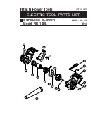
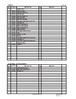
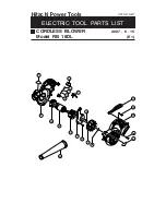
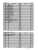
exploded assembly diagram for the Models RB 14DL and RB 18DL.
1. Removal of the fan
Be sure to draw on work gloves before holding the Fan
[15]
to prevent injury to fingers. Remove the Nozzle
[22]
from the main body. Remove the Tapping Screw D3.5 x 15 (Black)
[18]
and the Tapping Screw D3.5 x
20
[20]
that secure Housing (L)
[19]
to the casing. Remove the Nut M6
[16]
and pull out the Fan
[15]
from
the motor shaft.
2. Removal of the motor
After removal of the Fan
[15]
, remove the Tapping Screw D3.5 x 15
[14]
that secures the casing to Housing
(R)
[9]
. Remove the Machine Screw M4 x 10
[8]
that secures the casing to the Motor
[11]
, and remove the
Motor Plate
[13]
. Then the Motor
[11]
can be removed together with Motor Holder (A)
[12]
. In either case,
the Motor
[11]
can be removed by lightly tapping the end of Housing (R)
[9]
with a wooden hammer.
3. Disassembly of the power supply unit
Remove the Battery Holder
[7]
from Housing (R)
[9]
. The internal wires of the Micro Switch
[2]
and the
Motor
[11]
are soldered to the Battery Holder
[7]
. Unsolder and remove the internal wires.
REPAIR GUIDE
Disassembly

