background image

PARTS

P 20SF

   DESCRIPTION

    REMARKS

*

67

331-269

INTERNAL WIRE

1

FOR AUS, NZL, SAF, GBR, EUROPE, NOR, SWE, 

DEN, FIN, AUT, TUR, SUI, RUS, CHN, TPE, KOR

68

334-838

REAR BASE

1

69

307-811

TAPPING SCREW (W/FLANGE) D4 X 16 (BLACK)

4

*

70

976-815

MACHINE SCREW (W/WASHERS) M4 X 8

4

FOR IND

   DESCRIPTION

    REMARKS

*

501

334-693

SET GAUGE

1

FOR IND

502

940-543

BOX WRENCH 10 MM

1

503

958-842Z GUIDE

1

504

940-650

STOPPER SCREW M5 X 14

1

*

505

314-767

BLADE SHARPENING ASS'Y

1

EXCEPT FOR DOUBLE EDGE BLADE TYPE

*

506

334-735

CASE

1

FOR USA, CAN

*

506

334-475

CASE

1

FOR GBR, FRA, UAE, AUS, NZL

*

507

316-419

SET GAUGE

1

EXCEPT FOR IND

*

508

334-502

DUST ADAPTER

1

FOR USA, CAN

509

322-955

DUST BAG (BLACK)

1

   DESCRIPTION

    REMARKS

601

334-503

ELBOW

1

- 4 -

Printed in Japan

10 - 12

                                        (121012N) 

          *ALTERNATIVE PARTS

OPTIONAL  ACCESSORIES

STANDARD  ACCESSORIES

NO.

USED

CODE NO.

ITEM

NO.

CODE NO.

ITEM

NO.

NO.

USED

CODE NO.

ITEM

NO.

NO.

USED

CODE NO.

ITEM

NO.

NO.

USED

CODE NO.

ITEM

NO.

Содержание P 20SF

Страница 1: ...0SF 0675 Oct 2012 PRODUCT NAME Hitachi 82 mm 3 1 4 Planer Model P 20SF International Sales Division REPAIR GUIDE 1 1 Precautions on disassembly and reassembly 1 STANDARD REPAIR TIME UNIT SCHEDULES 6 CONTENTS Page P ...

Страница 2: ...e planer cutter in order to protect the tip of the cutter against damage and prevent the user from being injured 1 Disassembly of the armature cutter block ass y and end bracket Remove the Machine Screw Black M4 x 16 49 and Tip Cover 31 Then remove the Brush Cap 37 and Carbon Brush 36 Next remove the two Tapping Screws W Flange D4 x 12 Black 30 and Bearing Cover 29 Remove the two Machine Screws Bl...

Страница 3: ... the surface with a wooden hammer to pull out the Stator Ass y 47 3 Disassembly of pulley A and pulley B Remove the two Machine Screws Black M4 x 16 49 that secure the Belt Cover 39 to the End Bracket 42 and then remove the Belt Cover 39 Pulley A 50 and Pulley B 41 are fixed to the armature shaft and cutter spindle with left hand and right hand screws respectively Remove Pulley A 50 with the Armat...

Страница 4: ...25 to remove it Remove the four Tapping Screws W Flange D4 x 16 Black 69 on the Housing Ass y 59 to remove the Rear Base 68 5 Disassembly of the cutter block ass y from the end bracket Set the Cutter Block Ass y 1 18 in a vice and be careful to avoid damage remove Pulley B 41 and then strike the front edge of the spindle of the Cutter Block Ass y 1 18 to remove the Cutter Block Ass y 1 18 ...

Страница 5: ...f cm Brush Cap 37 1 0 0 5 N m 10 5 kgf cm Pulley A 50 8 0 1 0 N m 80 10 kgf cm Pulley B 41 8 0 1 0 N m 80 10 kgf cm Tapping Screws D4 21 30 32 53 69 2 0 0 5 N m 20 5 kgf cm Connect the wires as illustrated in the figure below Be careful to avoid inoperative rotation or a short circuit due to defective wiring Reassembly Connecting diagrams Tightening torque For Taiwan China Korea New Zealand Austra...

Страница 6: ...ing disassembly and repair measure the insulation resistance and conduct a dielectric strength test After no load operation for 30 minutes the no load current values should be as follows Voltage V 110 120 220 230 240 Current A max 2 3 to 3 1 2 2 to 3 0 1 3 to 1 9 1 0 to 1 5 1 0 to 1 5 Product accuracy Insulation tests No load current value ...

Страница 7: ... Bearing 6200VV x 2 Ball Bearing 608VV x 2 Cutter Block Ass y 1 Cutter Block Ass y 2 Stator Ass y Housing Ass y Work Flow Belt Pulley B Pulley A Switch Cord Armor Cord Planer Blades 1 Blade Holder 1 Planer Blades 2 Blade Holder 2 Bolt M6 1 Replaceable blade specification 2 Grinding blade specification STANDARD REPAIR TIME UNIT SCHEDULES ...

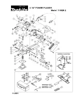
Страница 8: ... 8 9 20 21 22 23 24 25 26 27 28 30 29 49 31 33 34 35 36 37 38 9 8 14 15 16 11 12 13 17 16 15 14 13 12 11 9 8 19 57 47 46 45 44 42 41 40 39 50 49 59 60 61 56 55 53 54 52 51 32 62 63 67 66 64 68 69 501 502 503 504 505 506 507 32 A A 48 32 58 10 18 5 1 4 6 7 8 9 6 65 508 509 ...

Страница 9: ... TYPE FOR IND 17 608 VVM BALL BEARING 608VVC2PS2L 1 18 334 481 CUTTER BLOCK ASS Y W B B 1 INCLUD 11 13 17 19 EXCEPT FOR DOUBLE EDGE BLADE TYPE FOR IND 19 620 0VV BALL BEARING 6200VVCMPS2L 1 20 958 945 SCREW PLATE 1 21 954 004 TAPPING SCREW D4 X 16 1 22 958 709 SPRING 1 23 958 708 RUBBER PACKING 1 24 334 739 FRONT BASE 1 25 334 494 KNOB A 1 26 334 497 LOCK NUT M10 1 27 334 488 KNOB B 1 27 334 489 K...

Страница 10: ...NG 608VVC2PS2L 1 58 331 707 FASTON 1 59 334 482 HOUSING ASS Y 1 INCLUD 20 21 33 35 59 334 483 HOUSING ASS Y 1 INCLUD 20 21 33 35 FOR USA CAN 60 953 327 CORD ARMOR D8 8 1 61 500 409Z CORD 1 CORD ARMOR D8 8 61 500 247Z CORD 1 CORD ARMOR D8 8 FOR NOR SWE DEN FIN 61 500 432Z CORD 1 CORD ARMOR D8 8 FOR USA CAN MEX PAN 120 V 61 500 231Z CORD 1 CORD ARMOR D8 8 FOR SIN MAL UAE 61 500 455Z CORD 1 CORD ARMO...

Страница 11: ...8 842Z GUIDE 1 504 940 650 STOPPER SCREW M5 X 14 1 505 314 767 BLADE SHARPENING ASS Y 1 EXCEPT FOR DOUBLE EDGE BLADE TYPE 506 334 735 CASE 1 FOR USA CAN 506 334 475 CASE 1 FOR GBR FRA UAE AUS NZL 507 316 419 SET GAUGE 1 EXCEPT FOR IND 508 334 502 DUST ADAPTER 1 FOR USA CAN 509 322 955 DUST BAG BLACK 1 DESCRIPTION REMARKS 601 334 503 ELBOW 1 4 Printed in Japan 10 12 121012N ALTERNATIVE PARTS OPTION...

Отзывы: