


-29-
•
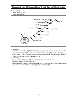
Disassembly and reassembly of the adjuster section
Adjuster
[76]
Adjuster Plate (A)
[80]
Adjuster Plate (C)
[79]
Adjuster
Spring
[78]
Pushing Lever (B)
[82]
Convex portion
Bent part
Adjuster Plate (A)
[80]
bent part
•
Disassembly and reassembly of Nose, Pushing Lever (A), etc
Convex portion
of
Adjuster Plate (A)
[80]
Fit convex portion to concave portion.
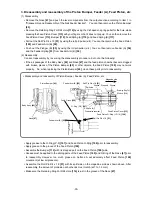
1. Disassembly and reassembly of Nose, Pushing Lever (A), etc
(1) Disassembly
•
Remove the four Nylock High Tension Bolts M7 x 25
[56]
. The Nose
[47]
and Pushing Lever (A)
[59]
can
then be removed.
•
Remove the Shaft Ring
[117]
of Nose Piece (A)
[122]
by using the slotted screwdriver. You can then
detach Nose Piece (A)
[122]
, the Nose Shaft
[119]
, two Nose Sleeves
[118]
, Spring
[121]
, Urethane
Shaft
[120]
and Nose Bumper
[116]
.
•
Remove the Shaft Ring
[117]
of the Change Knob
[48]
by using the slotted screwdriver. You can then
detach the Change Knob
[48]
.
•
When detached, the Nose Bumper
[116]
has weak adhesive force. If the Nose Bumper
[116]
must be
detached, you must order a new one, clean and degrease the bumper site, adhere it to the end of the
Nose
[47]
, and then press-fit it to the site. Orient the bumper correctly.
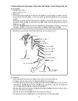
(2) Reassembly
Conduct reassembly by reversing the disassembly procedure, but note the following:
•
Apply grease to the O-Ring (S-34)
[46]
and O-Ring (1AP-3)
[106]
, fit both to the outer periphery of the
inlaid part of the Nose
[47]
, and carefully conduct reassembly.
•
Match the bent part of Adjuster Plate (A)
[80]
with the depression of the Pushing Lever Guide
[70]
for
reassembly.
•
After reassembly, make sure the push lever components and Adjuster
[76]
move smoothly.
•
Apply grease to Nose Piece (A)
[122]
and the two Nose Sleeves
[118]
.at reassembly. Be careful not
to lose the two Nose Sleeves
[118]
.
2. Disassembly and reassembly of the adjuster section
(1) Disassembly
•
Remove the Retaining Ring (E-Type) For D3 Shaft
[84]
. You can then disassemble the Adjuster
[76]
section into Pushing Lever (A)
[59]
, Pushing Lever Cover (B)
[58]
, and Adjuster
[76]
components.
•
Pull out the Roll Pin D2 x 16
[77]
by using the roll pin puller (ø 2). You can then disassemble the
Adjuster
[76]
section into its components.
(2) Reassembly
Conduct reassembly by reversing the disassembly procedure, but note the following:
•
Reassemble with the bent portion of Adjuster Plate (A)
[80]
facing towards the Adjuster
[76]
.
•
Reassemble with the convex portion of Adjuster Plate (C)
[79]
facing Adjuster Plate (A)
[80]
.
Pushing Lever Guide
[70]
Adjuster
[76]
Pushing Lever (A)
[59]
Nose Bumper
[116]
Nose
[47]
End face of Nose
[47]


