


-22-
Body Ass'y
[42]
Steel Ball D3.175
[101]
Pin D2 x 8
[85]
Feeder Shaft Ring
[41]
Trigger
[68]
Trigger Spring
[66]
Pushing Lever Guide
[70]
Trigger Piece (C)
[65]
Trigger Spring
[69]
Trigger Arm (C)
[67]
Roll Pin D1.6 x 10
[71]
Roll Pin D3 x 28
[100]
Machine Screw (W/Washers)
M5 x 25 (Black)
[105]
Roll Pin D3 x 28
[100]
Lock Knob
[103]
Lock Spring
[102]
O-Ring (S-14)
[86]
O-Ring (S-16)
[87]
Valve Bushing (B)
[88]
O-Ring (P7-U)
[89]
O-Ring (P9-U)
[90]
Valve Piston
[91]
O-Ring (1AP-11)
[92]
Plunger Spring
[93]
O-Ring (I.D 1.8)
[94]
Plunger
[95]
O-Ring (1AP-5)
[96]
O-Ring (S-6)
[97]
Valve Bushing (A)
[98]
O-Ring (S-16)
[87]
Roll Pin D2.5 x 16
[72]
Valve Bushing
(B)
[88]
Valve Bushing (A)
[98]
Pin D2 x 8
[85]
Flat-blade
screwdriver
Plunger
[95]
Valve Piston
[91]
Pin D2 x 8
[85]
•
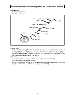
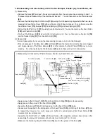
Disassembly of control valve section
[Tools required] •
Roll pin puller (ø 3, ø 2.5)
•
Flat-blade screwdriver
(1) Disassembly
•
Remove the Feeder Shaft Ring
[41]
. The Lock Knob
[103]
then comes off.
•
Pull out the Roll Pin D3 x 28
[100]
. The Pushing Lever Guide
[70]
and trigger section can then be
removed. Pull out Roll Pin D2.5 x 16
[72]
. The components of the trigger section can then be
removed.
•
Pull out the two Roll Pins D3 x 28
[100]
by using the roll pin puller (ø 3), and then remove the control valve
section by following the procedure below.
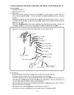
(a) Insert the tip of the flat-blade screwdriver into the
groove of Valve Bushing (A)
[98]
and lift up Valve
Bushing (A)
[98]
as shown on the left by applying
the principle of leverage with the body as the
supporting point.
NOTE: To protect the body, place a piece of
cloth between the screwdriver shank
and the body.
(b) After removing the two Pin D2 x 8
[85]
by using a
slim rod (ø 1.8), you can detach Valve Bushing (B)
[88]
, the Valve Piston
[91]
, Plunger Spring
[93]
,
and Plunger
[95]
.
NOTE: Never use pliers to clamp the Plunger
[95] end and pull it out.
The O-Ring (P9-U) [90] is very hard. Be
careful not to damage its periphery by
using a precision screwdriver or similar
tool.
Disassembly and Reassembly of the Control Valve Section


