


--- 26 ---
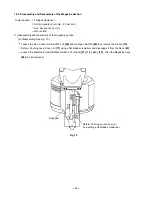
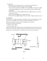
Wire with 1.5 to 3 mm dia.
(0.059" to 0.118")
Valve Bushing (B) [53]
Fig. 16
Hole
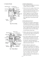
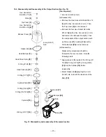
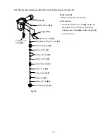
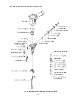
Pull out the Roll Pin D3 x 28 [38] with the roll
pin puller (3 mm (0.118") dia.), and take out the
control valve in the following manner.
1) Remove the Exhaust Cover [5] by following
the procedure in (1), section 10-2.
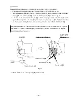
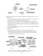
2) As shown in Fig. 15, put a 4 to 5 mm (0.157 to
0.197") dia. bar in from the upper side of the
Body [18] and push the top of Valve
Piston (B) [57]. Now, the parts forming the
control valve can be taken out except Valve
Bushing (A) [61] and Head Valve O-Ring
(I.D 16.8) [52].
[CAUTIONS]
Be careful not to damage Valve Piston (B)
[57], Valve Bushings (A) [61] and (B) [53], etc.
Do not pull out the end of Plunger (A) [59]
with pliers.
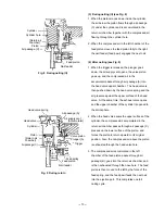
3) To take out Valve Bushing (B) [53], put a 1.5 to
3 mm (0.059" to 0.118") dia. wire with its end
hooked into the hole in the bushing and pull it
out while being careful not to damage the
internal surface of Valve Bushing (B) [53],
as shown in Fig. 16.
Be careful not to
damage the internal
surface.
Valve Bushing
(B) [53]
Plunger (A) [59]
Push
Head Valve
O-Ring (I.D 16.8)
[52]
4 to 5 mm (0.157" to 0.198")
dia. bar
Body [18]
Valve Bushing (A) [61]
Valve Piston (B) [57]
Fig. 15
When disassembling,
do not pull out this
part by gripping it
with pliers.
Содержание NV 75AG
Страница 45: ......