background image

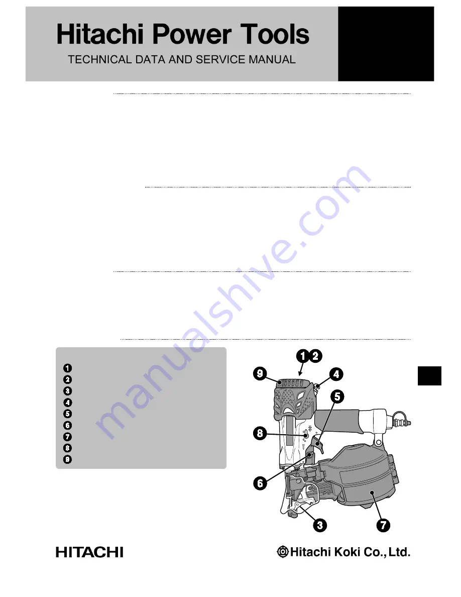
The new Model NV 65HMC is a high-pressure type [2-1/2" (65 mm)] of coil nailer. High-pressure nailer series
products have already been introduced to the Japanese market and become popular nationwide. This new
product offers higher punching force about three times greater than that of conventional nailers, in order to
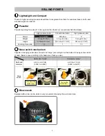
reduce its size and weight. The new Model NV 65HMC also features strong punching force, a nose switch
mechanism, blow nozzle, dual action trigger, and a tool-less adjuster.    Please expand sales of the new Model
NV 65HMC Nailer.

PRODUCT NAME

Hitachi 2-1/2” High Pressure Coil Nailer

Model


NV 65HMC

• Floor and wall framing
• Truss and window built-up
• Subflooring and roof decking
• Crate and pallet construction

MARKETING OBJECTIVE

APPLICATIONS

SELLING POINTS

SPECIFICATIONS AND PARTS ARE SUBJECT TO CHANGE FOR IMPROVEMENT.

LIST No.
NV 65HMC: E062
Dec. 2009

International Sales Division

N

[NEW FEATURES]

Lightweight and Compact
Powerful
Nose switch mechanism
Blow nozzle
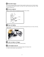
Dual action trigger
Tool-less adjuster
Easy nail loading
Lock mechanism of trigger
Low exhaust pressure

Содержание NV 65HMC

Страница 1: ...e dual action trigger and a tool less adjuster Please expand sales of the new Model NV 65HMC Nailer PRODUCT NAME Hitachi 2 1 2 High Pressure Coil Nailer Model NV 65HMC Floor and wall framing Truss and window built up Subflooring and roof decking Crate and pallet construction MARKETING OBJECTIVE APPLICATIONS SELLING POINTS SPECIFICATIONS AND PARTS ARE SUBJECT TO CHANGE FOR IMPROVEMENT LIST No NV 65...

Страница 2: ... hitachi koki com manual_view_export Throughout this TECHNICAL DATA AND SERVICE MANUAL a symbol s is are used in the place of company name s and model name s of our competitor s The symbol s utilized here is are as follows Competitors Symbols Utilized Company Name Model Name P MAX HN65 ...

Страница 3: ...ual Action Trigger 6 COMPARISON WITH SIMILAR PRODUCTS 7 1 Comparison of Specifications 7 PRECAUTIONS ON SALES PROMOTION 8 1 Safety Instructions 8 TROUBLESHOOTING GUIDE 10 1 Troubleshooting and Repair 10 2 Possible Causes and Corrections of Air Leakage 15 REPAIR GUIDE 18 1 Precautions on Disassembly and Reassembly 18 Assembly Diagram for NV 65HMC ...

Страница 4: ... lbs Height 28 5mm 11 1 4 300 mm 11 13 16 301 mm 11 7 8 Punching force ratio 1 3 1 1 3 Nose switch mechanism Capable of changing outlet sizes Small and Large according to nail head sizes for using various kinds of nails Select a nose according to the head size of nails you use Outlet size Small Outlet size Large Nail head diameter ø 4 8 to ø 6 0 mm 0 189 to 0 236 ø 6 0 to ø 7 3 mm 0 236 to 0 287 N...

Страница 5: ... adjuster adjusts the nailing depth sink quantity of the nail head Easy nail loading When you open the nail magazine cover the nail holder automatically tilts toward you so that you can easily change nail rolls Lock mechanism of trigger This lock mechanism locks the trigger so that it cannot be pulled Low exhaust pressure A muffler is provided to break the force of exhaust and suppress the blowing...

Страница 6: ...e type Packaging dimensions Length x Height x Width 355 mm x 410 mm x 170 mm 14 x 16 x 6 11 16 Standard accessories Case Code No 886432 Eye protector Code No 875769 Oiler 30 cc Code No 883136 Nose cap Code No 886650 Optional accessories Pneumatic tool lubricant 1 oz oil feeder Code No 877153 Pneumatic tool lubricant 4 oz oil feeder Code No 874042 Pneumatic tool lubricant 1 Code No 876212 NOTE The ...

Страница 7: ...ng energy required for punching nails flush Air pressure exceeding the intersecting point between nailer output energy and the required nailing energy for punching nails ensures fully punched nails For example when punching a nail measuring 3 1 mm in dia x 65 mm in length 0 122 x 2 1 2 into a workpiece of hemlock with the Model NV 65HMC pressure of about 14 7 bar 15 kgf cm2 210 psi enables the nai...

Страница 8: ... 20 J ft lb kgf cm 23 20 17 14 11 100 80 60 40 1000 800 600 400 200 80 60 40 20 20 J ft lb in2 mm2 bar psi kgf cm2 kgf cm 23 20 17 14 300 250 200 150 11 L d Air pressure setting to punch nail flush with NV 65HMC Size of Nail mm in 3 1 x 65 122 x 2 1 2 Nail d x L mm x mm 120 350 Hemlock Required nailing energy Nailer output energy 1200 1200 5 ...

Страница 9: ...n 3 Nail driven Single sequential actuation mode Depress the pushing lever Pull the trigger Driven Depress the pushing lever Not driven Contact action mode Pull the trigger Depress the pushing lever Driven Depress the pushing lever Driven 2 Precautions on using the dual action trigger Nails are not punched even with the pushing lever again pressed against the workpiece and the trigger pulled in si...

Страница 10: ...ine type Top loading Easy nail loading Bottom loading Top loading Blow nozzle Provided None None Driving depth adjustment mechanism Tool less Tool less Tool less Single actuation contact actuation selector Automatic None Automatic Nose cap Provided Provided Provided Free angle plug None None Provided Outlet size Switching type ø 6 5 mm ø 8 mm Fixed type ø 6 4 mm Replacement type ø 6 4 mm ø 7 6 mm ...

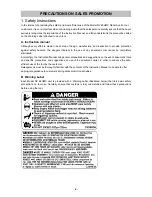
Страница 11: ...n the use of any pneumatic tool cannot be completely eliminated Accordingly the Instruction Manual lists general precautions and suggestions on the use of pneumatic tools and specific precautions and suggestions on use of the pneumatic nailer in order to enhance the safe efficient use of the tool by the customer Salespersons must be thoroughly familiar with the contents of the Instruction Manual t...

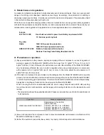
Страница 12: ...r Otherwise the performance service life and safety of the Model NV 65HMC may be adversely affected Be sure to install a regulator when using a high pressure air compressor with pressure set to 23 kgf cm2 320 psi 23 bar or more In this case adjust the air pressure to 23 kgf cm2 320 psi 23 bar or less 2 If the dust in compressed air accumulates on the sliding portion the Model NV 65HMC will not ope...

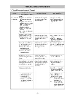
Страница 13: ... damaged or fatigued Feeder is abnormal damaged or worn Check that the punching section is not abnormal burrs deformed damaged or worn Deburr the nail guide face Correct the deformed part Replace abnormal parts Nails are not correctly loaded in the groove of the nose Check that nails are correctly loaded in the groove of the nose Load nails in the correct position in the nose Dust adheres to the f...

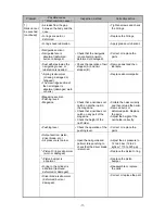
Страница 14: ...g lever Magazine Check that a nail does not catch on another nail in the magazine Check that a nail does not catch on any part of the magazine Check the height of the nail holder Collate the nails correctly and then reload the nailer Remove burrs or deformed parts Replace the parts Adjust the height of the nail holder correctly Pushing lever Check the operation of the pushing lever Correct or repl...

Страница 15: ...control valve section and check the O rings Replace abnormal parts Apply grease Adjuster is raised too high for short nails Check that the adjuster is not raised too high Turn the adjuster lower lower the pressure Nails are not completely fed into the injection port Unspecified nails are used See item 1 See item 1 Driver blade is worn Check that the driver blade tip is not abnormally worn Replace ...

Страница 16: ... lubrication Replace abnormal parts Apply grease Check whether the specified nails are used Check the nails as follows Use specified nails Remove abnormal nails and load the nailer with proper nails 4 Nails jam Nails Unspecified nails are used Abnormal nails are mixed Nail heads are too large or too small Wire collated nails Collating wires are abnormal broken failed welding deformed or failure at...

Страница 17: ... Replace abnormal parts Body Nail guide section Nail guide section is abnormal See item 1 Nail guide section See item 1 Nail guide section Driver blade does not return completely See item 1 Output section piston driver blade etc Perform idle or actual punching to check whether the driver blade returns completely See item 1 Output section piston driver blade etc 4 Nails jam continued Air pressure i...

Страница 18: ... 15 Air leakage repair location OFF ON Magnified view of Z Control valve section 2 Possible Causes and Corrections of Air Leakage 1 Air leakage repair location ...

Страница 19: ...xhaust Cover 7 worn deformation or cracks Defects on Exhaust Rubber 13 breaks deformation or flaws Defects on Head Valve 10 seal surface breaks deformation or flaws on the seal surface Defects on O Ring 11 deformation or flaws on part Exhaust cover near the head guard Loose Nylock Bolt M5 x 25 6 Break in Gasket 14 Defects on Body Ass y 39 and Exhaust Cover 7 seal surfaces breaks deformation or fla...

Страница 20: ...tion flaws on part Defect on the inner surface of Body Ass y 39 valve chamber part Control valve section Defect on O Ring S 16 96 and O Ring S 6 100 of Valve Bushing A 101 worn cut or flaws Defect on sliding surface of Plunger 93 O Ring S 6 100 deformation or flaws on part Defect on O Ring S 16 96 and O Ring S 6 100 of Valve Bushing A 101 worn cut or flaws Defect on sliding surface of Plunger 93 O...

Страница 21: ... to damage it and keep the O ring and its groove clean Apply grease Attolub No 2 to the inner surface of Cylinder 23 Replace a broken Gasket 14 with a new one and make sure it does not leak any air Always keep the control valve section away from any contaminant Apply the supplied oil to the nail feeding slide section When replacing Piston Bumper 41 be sure to check and make sure the air channels o...

Страница 22: ...n ten detach the Exhaust Cover 7 To remove the Exhaust Cover 7 turn and pull it up while holding the Body Ass y 39 NOTE Do not strike the side of the cover with a hammer to forcibly remove it from the Body Ass y 39 Doing so may damage the fitting parts To remove the Separator 18 from the Exhaust Cover 7 insert the flat blade screwdriver into the bottom of the Exhaust Cover 7 as shown below and pul...

Страница 23: ... Cover 7 until it is completely seated as shown to the left 2 Disassembly and reassembly of the Cylinder Piston H Piston Bumper etc Tools required Flat blade precision screwdriver 1 Disassembly Remove the Exhaust Cover 7 according to Disassembly and reassembly of the Exhaust Cover 7 Head Valve 10 Exhaust Rubber 13 etc You can then detach the Cylinder 23 Piston H 16 Piston Bumper 41 and other parts...

Страница 24: ...m the Valve Bushing 26 2 Reassembly Conduct reassembly by reversing the disassembly procedure but note the following Fully apply grease to the respective O rings Mount the Retaining Ring E Type For D4 Shaft 25 on the Plunger 30 and then push the Knob 24 straight in until it contacts the Retaining Ring E Type For D4 Shaft 25 Exhaust Cover 7 Knob 24 O Ring 1AP 3 29 O Ring S3 28 O Ring S 10 27 Spring...

Страница 25: ...3 You can then detach the Pushing Lever Guide 71 Trigger 69 section and Trigger Spring 70 After pulling out the Roll Pin D2 5 x 16 76 you can detach the components of the Trigger section Pull out the two Roll Pins D3 x 28 65 from the control valve section by using the roll pin puller ø 3 and then follow the instructions below to remove the control valve section a Insert the tip of the flat blade s...

Страница 26: ... x 8 94 into both For reassembly on the Body Ass y 39 first insert the roll pin puller ø 3 by making sure the pin passes through the roll pinhole and then hammer in the two Roll Pins D3 x 28 65 Orient the splitting of Roll Pin D3 x 28 65 as shown below at reassembly NOTE Always match the roll pin groove of Valve Bushing A 101 with the roll pinhole of the Body Ass y 39 before hammering in the roll ...

Страница 27: ...2 5 x 16 76 with its splitting oriented as shown below For easier reassembly of the Trigger section onto the Body Ass y 39 mount the Trigger Spring 70 and Trigger section onto the Pushing Lever Guide 71 in advance by using the ø 3 x 19 rod Orient the splitting of the Roll Pin D3 x 28 65 as shown above at reassembly Be careful not to reverse the insertion direction of the Roll Pin D3 x 28 65 when r...

Страница 28: ...wdriver or similar tool 2 Reassembly Conduct reassembly by reversing the disassembly procedure while fitting the convex portion of the Magazine 132 to the Nose 43 Fold back the Cover 118 twice fit its hole to the convex portion of the Magazine 132 and then press it with Pushing Lever Cover B 134 The Cover 118 must be located outside Pushing Lever Cover B 134 This nailer has its Name Plate 139 atta...

Страница 29: ...Pushing Lever Cover B 134 Hex Socket Hd Bolt M5 x 20 111 Ratchet Spring 140 Spring 145 Holder Cap A 141 Change Knob 44 Lock Spring 45 Shaft Ring 112 Steel Ball D3 175 46 Spring 114 Nose Piece 116 Nose Shaft 115 Shaft Ring 112 Concave portion Locate the hole of the Cover 118 between the convex portion of the Magazine 132 and the concave portion of Pushing Lever Cover B 134 Cover 118 Pushing Lever C...

Страница 30: ... D2 5 x 12 143 by using the roll pin puller ø 2 5 mm The Nail Holder 142 Holder Shaft 144 and Spring 145 can then be removed 2 Reassembly Conduct reassembly by reversing the disassembly procedure but note the following While reassembling the Holder Shaft 144 onto the Magazine 132 make sure the Spring 145 is correctly located between the concave portion of the Magazine 132 and the convex portion of...

Страница 31: ... Feed Piston Cover 109 Retaining Ring For D24 Hole 110 Pushing Lever C 73 Adjuster 74 Roll Pin D2 x 16 77 Adjuster Spring 81 Adjuster Plate C 82 Adjuster Plate A 83 Pushing Lever B 85 O Ring S 5 86 Retaining Ring E Type For D3 Shaft 87 Needle Roller 47 Change Knob 44 Lock Spring 45 Steel Ball D3 175 46 Hex Socket Hd Bolt M5 x 20 111 Spring 114 Nose Shaft 115 Shaft Ring 112 Nose Piece 116 O Ring S ...

Страница 32: ...t reassembly by reversing the disassembly procedure but note the following Apply grease to the O Ring S 38 42 fit it to the outer periphery of the inlaid part of the Nose 43 and then carefully reassemble Fit the convex portion of Adjuster Plate A 83 to the groove of the Pushing Lever Guide 71 and then reassemble After reassembly make sure the push lever components and Adjuster 74 move smoothly 2 D...

Страница 33: ... Roller 47 by using the roll pin puller ø 4 You can then remove Feeder A 51 and the Feeder Spring 50 from Feeder Arm B 49 2 Reassembly Conduct reassembly by reversing the disassembly procedure but note the following If the air passages of the Body Ass y 39 and Nose 43 and the feed piston chamber become clogged with broken pieces of the Piston Bumper 41 or other objects the Feed Piston 105 may not ...

Страница 34: ...x Socket Hd Bolt M4 x 10 126 by using the Hex bar wrench 3 mm You can then detach the Nail Guide Cover 117 Nail Stopper Spring 123 Stopper Spring 125 and Cover 118 Remove the Shaft Ring 112 of the Guide Lock 119 by using the flat blade screwdriver and then pull out Guide Lock 119 You can remove Nail Stopper A 122 and Nail Stopper B 124 2 Reassembly Conduct reassembly by reversing the disassembly p...

Страница 35: ... by your fingers and make sure the Plunger 30 moves smoothly Turn the Change Knob 44 and make sure the size of the ejection port varies correctly 2 Connect compressed air to the nailer and confirm the following No air leaks from any part of the nailer The nailer is inactive when you pull the Trigger 69 while the Lock Knob 80 is in the Free position The nailer does not work when Pushing Lever A 55 ...

Страница 36: ...2 47 48 49 50 51 53 54 55 56 57 58 63 59 60 65 64 61 62 66 67 69 70 71 72 73 74 77 75 76 78 79 80 81 82 83 84 85 86 87 88 89 90 91 92 93 94 95 96 97 98 99 100 101 96 102 103 105 104 106 107 108 109 110 111 113 114 115 116 112 121 119 120 122 123 124 125 112 117 118 126 127 128 130 129 135 57 133 134 136 135 136 137 138 139 132 141 143 144 145 502 503 112 146 132 135 137 145 43 142 140 501 39 131 1...

Страница 37: ...3 886 415 CYLINDER 1 24 884 334 KNOB 1 25 968 643 RETAINING RING E TYPE FOR D4 SHAFT 1 26 885 027 VALVE BUSHING 1 27 987 105 O RING S 10 1 28 881 715 O RING S3 1 29 873 093 O RING 1AP 3 1 30 885 028 PLUNGER 1 31 878 607 PLUNGER O RING 1 32 881 900 SPRING 1 33 884 338 VALVE PACKING 1 34 931 835 O RING P 36 1 35 986 374 O RING P 32 1 36 886 669 FEEDER SHAFT RING 1 37 HITACHI LABEL B 1 38 883 513 WAR...

Страница 38: ...1 72 882 892 PUSHING LEVER SPRING 1 73 882 891 PUSHING LEVER C 1 74 882 889 ADJUSTER 1 75 886 228 ROLL PIN D1 6 X 10 1 76 881 951 ROLL PIN D2 5 X 16 1 77 880 093 ROLL PIN D2 X 16 1 78 959 148 STEEL BALL D3 175 10 PCS 1 79 882 923 LOCK SPRING 1 80 886 727 LOCK KNOB 1 81 882 890 ADJUSTER SPRING 1 82 884 973 ADJUSTER PLATE C 1 83 882 886 ADJUSTER PLATE A 1 84 981 317 O RING S 4 1 85 882 888 PUSHING L...

Страница 39: ...121 886 404 NAIL GUIDE 1 122 883 783 NAIL STOPPER A 1 123 886 451 NAIL STOPPER SPRING 1 124 882 680 NAIL STOPPER B 1 125 880 494 STOPPER SPRING 1 126 880 413 NYLOCK HEX SOCKET HD BOLT M4 X 10 1 127 882 881 SLEEVE B 1 128 880 630 NYLOCK HEX SOCKET HD BOLT M4 X 12 1 129 887 175 WARNING LABEL 1 130 LABEL D 1 131 887 174 WARNING LABEL 1 132 886 428 MAGAZINE 1 133 882 907 SLEEVE 1 134 883 762 PUSHING L...

Страница 40: ...NV 65HMC DESCRIPTION REMARKS 501 883 136 PNEUMATIC TOOL LUBRICANT 30 CC 1 502 875 769 SAFETY GLASSES 1 503 886 432 CASE 1 12 09 5 ALTERNATIVE PARTS STANDARD ACCESSORIES NO USED CODE NO ITEM NO ...

Страница 41: ...HMC DESCRIPTION REMARKS 601 881 768 GRIP TAPE A 1 602 880 407 TAPE 2 603 876 212 PNEUMATIC TOOL LUBRICANT 1 L 1 6 Printed in Japan 12 09 091211N ALTERNATIVE PARTS OPTIONAL ACCESSORIES NO USED CODE NO ITEM NO ...

Отзывы: